Hidden Math: The Numbers Behind LEGO Circles and Spheres
/What math is hidden in your favorite circular LEGO sets, how do designers build the perfect sphere, and how do numbers magically make LEGO geometry work so perfectly?
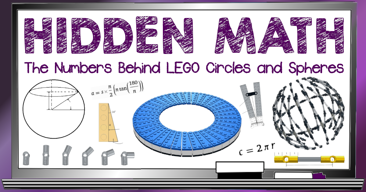
To help answer those questions, we are pleased to feature another guest article from Deep Shen, a well-rounded builder who discusses the hidden math of LEGO circles and spheres. Deep’s portfolio of work can be found at Towering Brick Creations, on his Flickr page and on Instagram.
A Shield and A Globe
In August 2023, LEGO released a new set (76262) that creates a reasonably accurate replica of Captain America’s Shield from the MCU (Marvel Cinematic Universe).

The initial fan reactions to this set were less than positive, with some people comparing it unfavorably to the bigger (and more expensive) custom version sold by Bricker Builds.

That particular version is built as a sculpture created by stacking regular plates, which makes it far more sturdy. The official set, on the other hand, is smaller and seems more flimsy. But there are many reasons to appreciate the new set, not the least of which is the clever way it uses wedge plates to create the round shape.
This is the second recent set (after LEGO Ideas 21332 Globe released in February 2022) that creates a round shape by attaching wedge plates at different angles over an inner frame.

There are indeed some obvious gaps between the wedge plates, but together these plates still do a great job of approximating the curved shape. While this is a relatively new technique as far as official LEGO sets are concerned, AFOLs have been using it for quite a while.
The Globe set, as you know, is an Ideas set that is based on a design by French AFOL Guillaume Roussel (@disneybrick). Another AFOL Pete Strege (@redcokid), who is a master at this technique, has used it to create an impressive array of MOCs including various buildings with round-shaped domes, a hot air balloon and even a flying pig!

Clearly, there is some interesting math at play here. I am a bit of a novice with this technique myself, but I couldn’t resist the challenge of trying to reverse-engineer the two official sets (the Globe and Captain America’s Shield) to try to uncover some of this math. And so, in this next installment of my Hidden Math series on BrickNerd, we will be delving into the numbers behind the Globe and Captain America’s Shield. We will try to understand conceptually how the outer shapes of the globe and the shield are put together (not necessarily following the instructions for the actual sets).
Before we start diving in, we need to get a few prerequisites out of the way – namely polygon geometry, an overview of the Technic pieces used to create the inner frame in the Globe set, and the wedge plates that are used in conjunction with regular plates to create the outer “skin” in both sets.
(If you want to skip the background numbers and jump to the geometry of the sets, skip the next three sections and head to “The Globe” section.)
Polygon Geometry
In my last article, we saw how LEGO hinge plates can be used to create angled walls. If we extend this concept further, we should also be able to build a continuous chain of angled wall segments that form a closed shape – namely, a polygon. Limiting our discussion to regular polygons (polygons where all the sides and angles are equal), how do we determine what the length of each side should be and ensure that at least one pair of opposite sides of the polygon line up with the LEGO grid (so that we have a way of attaching the polygonal wall to a baseplate)?
For this, we will have to first review the geometry of polygons and familiarize ourselves with a few basic terms.

A regular polygon has n (where n is three or more) sides of equal length. The point where any two adjacent sides intersect is called a vertex, and the angle they make at the vertex interior to the polygon is called the interior angle. In a regular polygon, all the interior angles are also equal. Shown here is a hexagon with six equal sides that we will be using for illustration purposes.

All regular polygons have a center that is equidistant from each of the vertices, and this distance is called the radius. If we draw lines from the center to each of the vertices, we would be dividing the polygon into n identical triangles. The angle made by the sides of the triangle that intersect at the center is called the central angle.

If you draw a circle with the same center and radius as the polygon, it will pass through each of the polygon’s vertices. This circle is called the circumcircle. It is also possible to draw a smaller circle with the same center that passes through the center point of each of the sides. This circle is called the incircle.

The radius of the incircle is equal to the length of lines drawn from the center that meet each of the sides at their center points. These lines are perpendicular to the sides and their length is called the apothem.
If we create a regular polygon using LEGO pieces, we need to ensure that the distance between any pair of opposite sides (which would be twice the apothem) is close enough to a whole number of studs. This will allow us to attach the polygonal wall firmly to a baseplate.
We can figure out how the apothem can be calculated if we know n (the number of sides) and the length of each side in studs. First, we will start with the central angle. If the polygon has n sides, the central angle would be 360/n. Since the sum of the angles in each of the n triangles would add up to 180° and the two other angles in the triangle are essentially identical halves of the interior angle, we can calculate the interior angle as 180 – 360/n which is sometimes written as ((n-2)*180)/n.
If we split one of the n triangles into two mirrored right angled triangles, the tangent of half the central angle would be equal to half the length of each side (the opposite side) divided by the apothem (the adjacent side), written as follows tan(360/2n) = s/2a or in mathematical notation:

That equation can be simplified to tan(180/n) = s/2a or:

So the formula for calculating the apothem ends up being a = s/(2*tan(180/n)) or:

You would need a scientific calculator for this, but you can also use one of the online calculators available to compute the apothem of your polygon. All you have to enter is the side length (in terms of studs) and the number of sides. One of these calculators is embedded below:
One thing to note is that when the polygon has a large enough number of sides, the polygon starts to approach a circle and the apothem (a) starts to approach the radius of the circle (r).
The equation for the apothem can be written as a = s*n/2*(n*tan(180/n)) or in mathematical notation:

It is beyond the scope of this article to explain why, but n*tan(180/n) starts to approach π as n gets larger. We can plug a few different values for n and confirm that the larger n is, the closer n*tan(180/n) gets to 3.14159… (the value of π). For a large enough value of n, we have a = s*n/2π or:

s*n is of course the sum of the lengths of the n sides which would approach the circumference of the circle (c) and that gets us to the familiar equation for the circumference of a circle of c = 2πr or:

And so, if the number of sides of our polygon is large enough (say 30 or more), we can get away with using this simpler equation to calculate the radius or diameter of our shape (as I have done in this article on round shapes).
LEGO Technic
Moving from math to LEGO, it is time to get Technic-al and discuss the elements that make up the structural core of both the Globe and Captain America’s Shield.
Technic Axles
LEGO cross-axles – commonly referred to as axles or rods with a cross-shaped cross-section – come in different lengths which are multiples of a LEGO stud. They are named based on their length in studs with L being the width of one LEGO stud (2L, 3L and so on). LEGO typically color codes their axles to make them easier to identify. The even-numbered lengths are in black or red, while the odd-numbered ones are in light bluish grey or yellow. Axles can be handy for connecting together different Technic elements including gears, wheels, etc.

Technic Axle and Pin Connectors
As the name implies, these axle and pin connector pieces can be used to make various connections either in a straight line or at an angle. They also have a hole that accepts a Technic pin. For this article, we will only focus on a particular family of angled axle and pin connectors that is made up of six types of pieces that are identified with numbers 1 through 6 (the pieces themselves are marked with these numbers on their sides). The angles that these pieces create range from 90° to 180°.

Here is a table showing all the pieces and the angle that each one creates. At first glance, the angles 112.5°, 135° and 157.5° may seem quite random but they really are not. In fact, if you divide the range between 90° and 180° into four equal parts, you would have angles separated by increments of 90/4 = 22.5° and the angles 112.5°, 135° and 157.5° start to make a lot more sense.
| Number | Part Number | Angle |
|---|---|---|
| 1 | 32013 | – |
| 2 | 32034 | 180° |
| 3 | 32016 | 157.5° |
| 4 | 32192 | 135° |
| 5 | 32015 | 112.5° |
| 6 | 32014 | 90° |
Now let us look at the dimensions of these connectors. The #2 connector (180° angle) is exactly three studs from end to end. When we use it to connect two axles together, the axles can go into the connector by as much as one stud on each side.

This leaves exactly one stud in-between for the portion that has the Technic hole. The distance from either end of the connector to the center of the Technic hole is 1.5 studs. The same is true for the angled connectors as well, and so if you wanted to have a distance of six studs between the holes on two connectors connected to either side of an axle, this axle would have to be five studs long (5L).
What practical uses can the different angles that these connectors create have in LEGO builds? Consider, for instance, the interior angle of a regular octagon. It is 180 – 360/8 = 180 – 45 = 135°. And so, we can use axles and #4 connectors to create an octagon. Using the apothem calculator, we see that the apothem of the octagon is close enough to a whole number of studs (6) when each side is 5 studs long. This means that we have to use 4L axles for the sides of the polygon.

Why does the apothem of the polygon have to be a whole number of studs even when we are using Technic pieces that do not get attached to a baseplate? The reason is that the frames constructed using Technic elements typically need internal structural reinforcement, and it is a lot easier to add this when the distance between the opposite sides of the polygon is a whole number of studs.
Let us next look at a regular polygon with 16 sides which is called a hexadecagon. The interior angle here is 180 – 360/16 = 180 – 22.5 = 157.5°. This means that we can use 16 of the #3 connectors to create the regular polygon with 16 sides. Each side can be 4 or 6 studs long for an apothem that is close enough to a whole number (10 or 15, respectively). The latter case is shown in the picture below with 5L Technic axles used for each of the 16 sides.

Connector #5 cannot be used to create a regular polygon. However it can be combined with the other types of connectors to create many different types of polygons. In fact, you can use the following numbering (which differs from the official LEGO numbering) to figure out the different ways in which the angled connectors can be used (the rule is for the numbers to add to a total of 16 to create a closed polygon).
| Number | Connector Type | Angle |
|---|---|---|
| 1 | #3 | 157.5° |
| 2 | #4 | 135° |
| 3 | #5 | 112.5° |
| 4 | #6 | 90° |
We have already seen how we can use eight of the #4 connectors (22222222) to create an octagon or 16 of the #3 connectors (1111111111111111) to create a hexadecagon. Using four of the #6 connectors (4444) to create a square or a rectangle is also a no-brainer. Some possible combinations that use the #5 connector are 333331, 33334 and 3322222. Shown below is the polygon created using 33334 (#5 and #6 connectors). Note that this is the smallest pentagon possible with one 90° angle and four 112.5° angles with side lengths that are each close enough to a whole number of studs (17, 17, 17, 17 and 11).

Technic Bush Pieces
A bushing or bush is a piece with a cross-shaped hole that can fit tightly over an axle. It comes in lengths of half a stud and one stud (named 0.5L and 1L respectively). It can be used to space pieces apart precisely in increments of half a stud or to hold pieces on the axle in place by acting as an end stop.

The LEGO catalog also includes variants of some of the axles (3L, 4L, 5L, 8L) that have an end stop built-in. These are typically available in colors like reddish brown and dark bluish grey which are different from the regular axles.

Technic bricks and plates with axle holes
It is clear that we can connect axles together using the connector pieces to create the internal framework for all kinds of shapes, but there is no way to create the outer skin for these shapes without having studs available to which we can attach LEGO plates. One way to create these studs is by using Technic bricks that have axle holes.

We can pass the axles that make up the frame through these bricks (positioning them correctly using bush pieces if needed) and this gives us a way to then attach LEGO plates to create the outer surface. However, when we are talking about a Technic framework that approximates a curved shape (like a globe), regular rectangular plates alone may not always work. This is where wedge plates can come into play.
Wedge Plates
Wedge plates are variants of regular LEGO plates except they have a portion that is truncated at an angle. There is a large number of wedge plates in the LEGO catalog with sizes ranging from 2×2 to 12×3. Each type of wedge plate (except the ones that create a 45° angle) comes in a left and a right variant (which is simply a mirror image of the left variant). Shown below is a sampling of the various wedge plates that are available.

The angle that the slanted edge of each wedge plate creates is easy to calculate using basic trigonometry (the truncated portion is a right triangle and so the tangent of the angle is equal to the opposite side divided by the adjacent side).

Since we know the lengths of the opposite and adjacent sides in terms of studs, we can find the inverse tangent (arctan) and assemble an entire table with the angles created by each type of wedge plate.
| Type | Part Number (Left) | Part Number (Right) | Opposite Side | Adjacent Side | Angle |
|---|---|---|---|---|---|
| 2×2 | 24299 | 24307 | 1 | 2 | 26.56° |
| 3×2 | 43723 | 43722 | 1 | 3 | 18.43° |
| 4×2 | 41770 | 41769 | 1 | 4 | 14° |
| 6×2 | 78443 | 78444 | 1 | 6 | 9.46° |
| 6×3 | 54384 | 54383 | 2 | 6 | 18.43° |
| 6×4 | 48208 | 48205 | 3 | 6 | 26.56° |
| 8×3 | 3544 | 3545 | 2 | 8 | 14° |
| 12×3 | 47397 | 47398 | 2 | 12 | 9.46° |
Now let us see how all these different types of LEGO elements can be put together to create the curved shapes of the Globe and Captain America’s Shield.
The Globe
If you look at the outer shape of the LEGO Globe, you will see that 1) the section in the middle (where the equator would be on a real globe) is made up of regular 6×6 plates, and 2) there are 16 of them used to approximate the round shape. If this looks familiar, that is because we have already seen a hexadecagon with a side length of 6 studs that can be created using 16 #3 (157.5°) connectors.

We need a 5L axle piece for each side of this hexadecagon and if we pass it through bricks with axle holes (see the instructions for the details) such that the studs on these bricks are facing outwards, we can attach the 6×6 plates needed to form the outer surface. Note that Technic 1×3 liftarms are also used in each of the 16 panels and these are connected together using 4L axles with stops for additional reinforcement.
You will notice that in the images that follow, the plates on the outer surface have a sand green color for illustration purposes. The actual globe set uses dark blue, which does not stand out as well in the renders (making it harder to see what is going on).
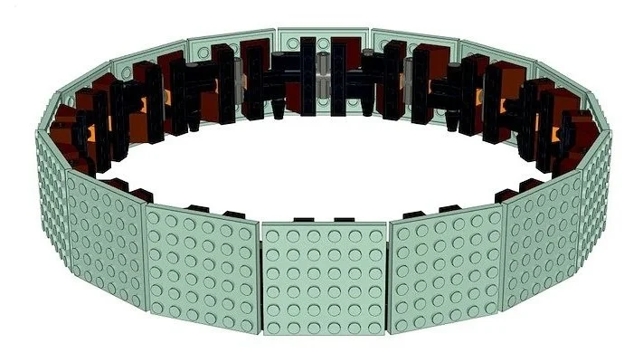
Now the globe is spherical, we need to create this same round shape in the other two dimensions as well. The first thought that comes to mind is – can we also create hexadecagonal rings in the vertical directions using the same #3 connectors? Yes, definitely. The way to attach these vertical rings to the horizontal one is by passing the horizontal 5L axles through the hole in a #2 (180°) connector placed vertically and then attaching it to #3 connectors placed on the top and bottom (using 2L axles).

This creates the same 6 stud spacing between the holes in the #3 connectors vertically that we get horizontally by using the 5L axle. So can we just create an intersecting set of rings in three dimensions and attach 6×6 plates to them?

That sounds reasonable but it doesn’t work very well in practice – especially since there is no good way to close the holes that remain.

Instead of trying of to use 6×6 plates throughout, we can create 16 wedge-shaped slices attached to the top and bottom of the central ring. These would taper as they reach the poles in each hemisphere. Of course, the best way to create these wedge-shaped slices is by using wedge plates.

But first, we have to create an internal frame to which we can attach these wedge-shaped slices. We can use the same method as before to create eight vertical rings that are attached to the 16 sides of our horizontal ring. Only this time, there is no way these rings can intersect at the poles, so we start with incomplete rings that stop well short of the poles. We will need to figure out a different way to connect the rings together at the poles.

Doing some quick back-of-the-envelope calculations lets us determine what kind of wedge plates we may need. We will again use plates that are six studs tall (based on the spacing between the Technic connectors in the vertical direction).
We can use the circle formula for these rough calculations even though the number of sides in our polygon is not very large. The circumference of the circle created by the existing row is 16×6 = 96 studs, and its radius works out to 96/2π which is roughly 15 studs. If we add another row of plates above the existing row, the circumference of the circle at the top edge of this second row would be roughly 80 studs. We can figure this out using the Pythagorean theorem.

The height from the equator to this smaller circle is roughly 3+6 = 9 studs. The line from the center of the sphere to this smaller circle is equal to the radius of the sphere which is the hypotenuse of a right triangle. One of the sides is the height which is nine studs and that gives us the radius of the smaller circle √(152-92) = 12. The circumference of this smaller circle is 2*π*12 = 75.36. Due to the curvature of the sphere, the plates will not be perfectly vertical, the actual height will be less than nine studs, and the circumference of the smaller circle will be more than 75.36. And so we should be fine rounding 75.36 to the next higher multiple of 16 which is 80.
80 divided by 16 is 5, and this means that we need each slice to taper from 6 studs to 5 studs. With the wedge plates that are available, it is easier to get a circumference of 80 studs by alternating 6 and 4 studs. We will therefore need to alternate a slice using 6×6 plates with a slice that uses wedge plates to create a taper from 6 to 4 studs (a 4×6 plate with 6×2 wedge plates on either side would do the trick).

For the row above this one, the circle at the top edge is even smaller working out to a circumference of roughly 48 studs. Instead of tapering each slice to 3 studs, we can get the same circumference by alternating 4 and 2 studs. This means that we alternate a slice that has a 4×6 plate with one that tapers from 6 studs to 2 studs (which is achieved using two 6×3 wedge plates).

Due to the curvature of the sphere, the third row above this would need to taper to an even smaller circle with a diameter of just 6 studs and a circumference of about 19 studs which is not a multiple of 16. The designers chose instead to use 10×10 dish pieces at the poles of the globe, and this means the third row has to be shorter (just 4 studs tall).
For this segment of the internal frame, a 4L axle piece is used instead of the 5L axle and there are clip pieces attached to the #3 connector closest to the pole. This allows us to attach all 16 slices to a round steering wheel piece placed at the poles. The dish piece with a diameter of 10 studs has a rough circumference of 32 studs, and this can be approximated using a hexadecagon with 2 studs on one side. Here, slices with 2×4 plates are alternated with slices that have two 2×4 wedge plates that together taper from 4 to 2 studs.

The steering wheel pieces have studs in the middle allowing us to top the globe off with the dish pieces at either end, that represent the north and south poles of the globe.

With that, we have a complete studs-out sphere ready to be decorated with details of your choosing.
Captain America’s Shield
The design of Captain America’s Shield set is again based on a polygonal shape. This time it is a polygon with 36 sides and each side is 2 studs long. This polygon is built using hinge bricks and plates which form the main core that the rest of the pieces are attached to, creating the round shape.

The central angle of the polygon is 360/36 = 10°. Looking at the table of angles created by wedge plates, we see that the 6×2 wedge plates create an angle of arctan(1/6) = 9.46° which is close enough to 10°. We can confirm this by attaching 6×2 wedge plates to the polygon so they point inwards. As you can see the wedge plates all fit nicely with minimal gaps.

If we create panels that extend outwards from the polygon while preserving the same angle, we can use them to make the circle as big as we need to (as long as we have a way to support each panel). The shield set creates a panel with four sections that are blue, red, white and red (going from the center outwards). Each section has to use the 6×2 wedge plate and is therefore 6 studs tall. But if we create the round shape using panels that flare in the same direction as shown below, we will end up with an outer edge that is a little jagged. We can do better than that!

So the LEGO designers decided to mix things up a bit by creating an alternating pattern of two different types of panels. In each of these panels, one of the two middle sections uses regular rectangular plates while the other uses two wedge plates to flare in both directions. This ensures that each panel doesn’t flare too much in any one direction and reduces the jaggedness in the outer edge.

The internal structure that these panels are attached to is created by using regular 2×14 plates that are attached to the sides of the polygon. These plates are strapped together using 1×4 plates that are attached 11 studs away from the rotation point of the hinges that make up the polygon.

We can confirm that the sides of the right triangle (with an opposite side that is one stud long and hypotenuse that is 11 studs long) create the necessary angle (5° which is half of the 10° angle between the 2×14 plates). sin(5°) = 0.087 which is close enough to 1/11 = 0.09.

The apothem of the polygon with 36 sides (and each side that is 2 studs long) turns out to be 11.43 studs (using the online apothem calculator). Given the large number of sides, we can simplify our calculations and treat the polygon as a circle with a circumference of 36×2 = 72 studs. The radius of this circle is 72/2π = 11.46 studs. The diameter (or the distance between any two opposite sides of the polygon) is close enough to 23 studs.
The Captain America’s Shield set uses Technic axles, bricks with axle holes and Technic 1×2 liftarms that are each half a stud thick to create a core structure that is 19×19 studs when measured between the outermost studs. This structure is attached two studs away from the sides of the polygon using 2×8 plates that point inwards for a total spacing of 19 + 2 + 2 = 23 studs.

The curvature of the shield is far more subtle than the curvature needed for the globe, so instead of using Technic connectors, the designers chose to simply use bricks, plates and interestingly some wedge plates placed sideways to create the internal structure. The panels that form the outer skin just rest on this internal support structure.

Each section of the panel uses plates with bar handles and clips allowing it to be hinged independently to achieve the curvature that is needed. The outermost section is also attached to the internal frame again using the same bar handle and clip method.

The math enables the shield to have as few jagged edges as possible. When completed, Captain America’s Shield is ready to break the laws of physics and fly through the air like a boomerang because the geometry of LEGO circles is so well done.
Conclusion
This technique (well, in all actuality it is taking advantage of LEGO math) uses wedge and normal plates in conjunction with an assortment of Technic elements to create curved shapes—a technique that has been used to great effect in two recent LEGO sets. Knowing the numbers behind the technique can help you make similarly round objects out of LEGO. So now you can build whatever curves you want!
Are you aware of any other official LEGO sets that use this technique? Is there a different technique that you would like me to explore in the next installment of this series? Let me know below!
What are other ways you have built circular objects out of LEGO? Let us know in the comments!
Do you want to help BrickNerd continue publishing articles like this one? Become a top patron like Charlie Stephens, Marc & Liz Puleo, Paige Mueller, Rob Klingberg from Brickstuff, John & Joshua Hanlon from Beyond the Brick, Megan Lum, Andy Price, Lukas Kurth from StoneWars, Wayne Tyler, Monica Innis, Dan Church, and Roxanne Baxter to show your support, get early access, exclusive swag and more.