All About NED: The LEGO Engineering Department You’ve Never Heard Of
/Yes, you read that title correctly—we did not misspell nerd! For Nerdvember, I am going to introduce you to NED. So, who in the world is NED!? To explain that, I first need to tell you about Bricks LA which began in 2015 and sadly held their last event in 2022. It was organized by Ayleen Dority. They had a great run of eight conventions, and it was even part of a small collective of conventions worldwide called Recognized AFOL Networking Events.
The last year of the convention brought us a behind-the-scenes look into something rarely seen: a presentation from LEGO engineers about NED, which stands for Novelty Element Development. The presentation came via video conference by Tore Christensen and Andreas Malling Jensen. They gave us a walkthrough of their daily activity and some example projects. This article aims to share that presentation with you and all the nerdy details!
Why does this presentation excite me? Besides getting a rare glimpse at what the LEGO engineers do, they function very similarly to the design and engineering team I manage at my job, working at a global plastics company. I’ll try to add bits and pieces from my experiences along the way as well. So, let’s dive right in with Tore and Andreas!
What Does NED Do?
Right away, we learned there are 26 engineers on staff at NED (it is a bit unclear if that is just the element design group). I personally expected a larger team, and it is presumably larger now given this presentation was from early 2022.
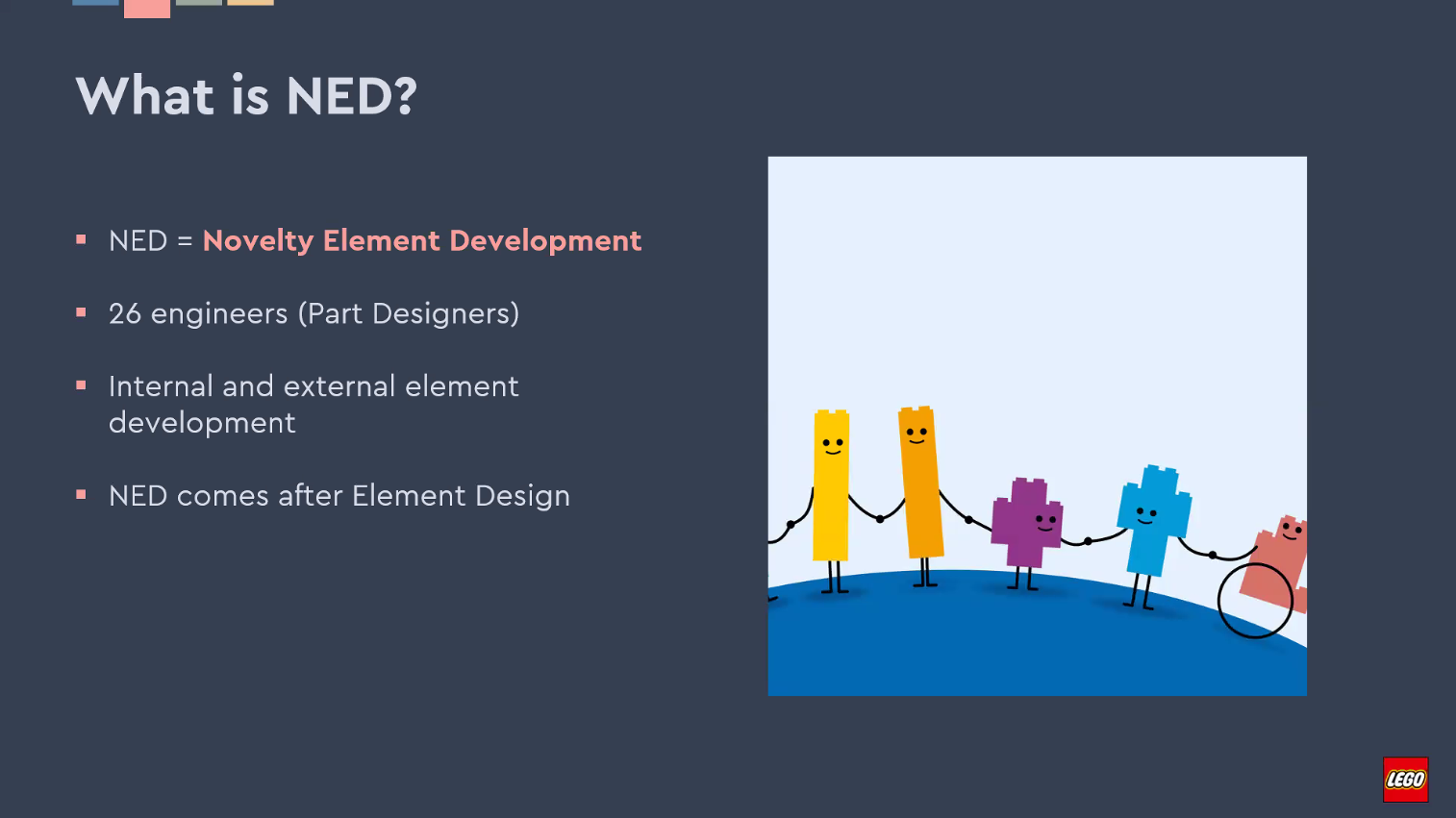
A portion of that engineering team works on external elements, which are defined as those elements that are manufactured by external partners and suppliers (think baseplates, electronics, etc.). The other team works on internal elements, meaning the elements that are molded internally by The LEGO Group. The NED team really comes into play after an element has already been developed collaboratively by the design and engineering teams. To read more about how the element development process begins, there are some fantastic interviews from New Elementary here and here!
In short, Tore and Andreas described the majority of what they do (and what we normally refer to in the industry as) design for manufacturability (DFM). They design parts in CAD from scratch, guided by what the element design team has specified they are looking for. Some of their tasks include checking part designs to make sure they are moldable, determining the optimal location for the injection gate (inlet), verifying the draft angles are adequate, the surfaces are perfect, and everything is within system specification, and of course, ensuring the parts are going to be within their safety standards for children and much more.
Simply put, NED is the bridge between design and manufacturing
Fixing A Quality Issue
To better explain what process they go through, Tore showed a quality issue with existing Duplo part 73540 Track Raised Ramp which was cracking under too much pressure.
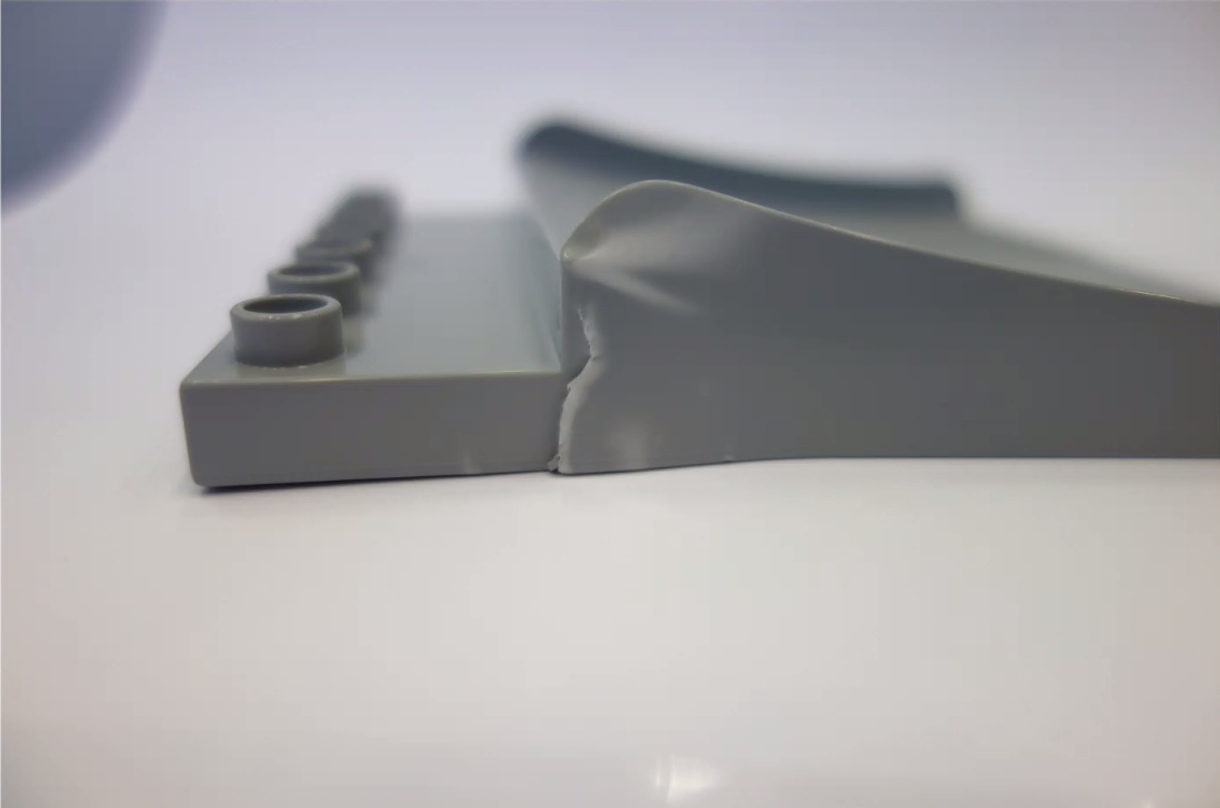
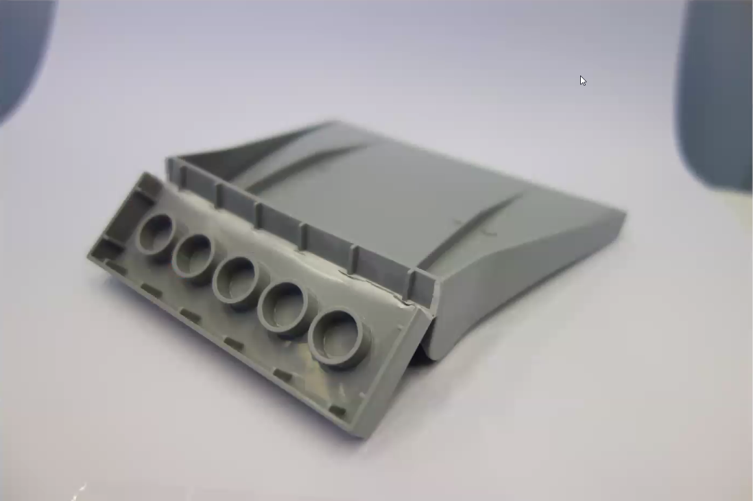
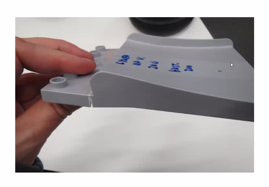
With a quick assessment, the team understood there would need to be reinforcement in that weak area by adding a rib structure underneath. Tore opened the element in a CAD design software (here we get to see they are using Siemens NX, the go-to modeling software when you are designing products requiring a Class A surface finish). He began showing us a comparison between the current failing part and the new adjustments which are highlighted in green in later slides.
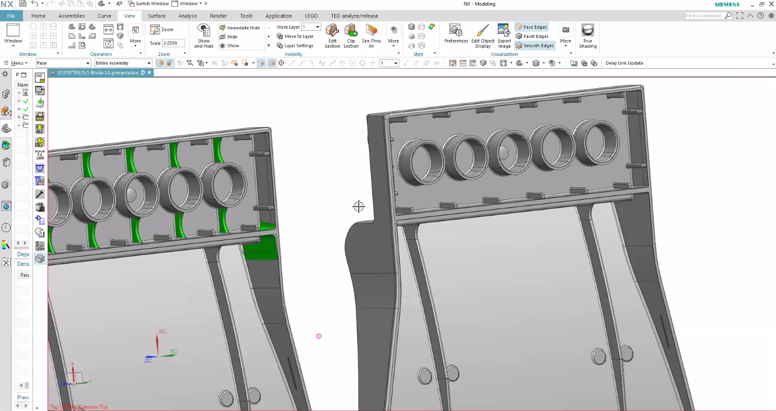
You can see the ribs added on the left part which connect the outer walls to the anti-stud tubes to will greatly reinforce the part! A couple of internal radii were also increased which gives better stability at the corners (which are common failure points).
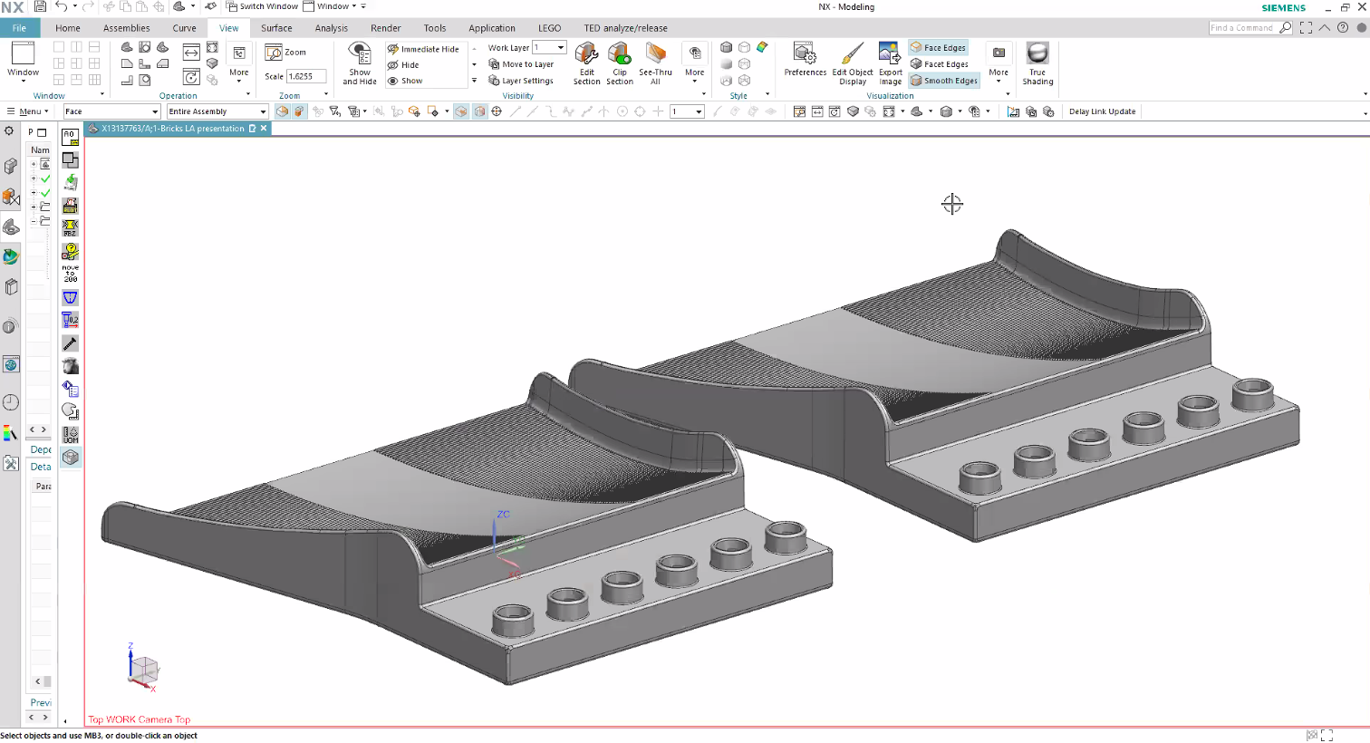
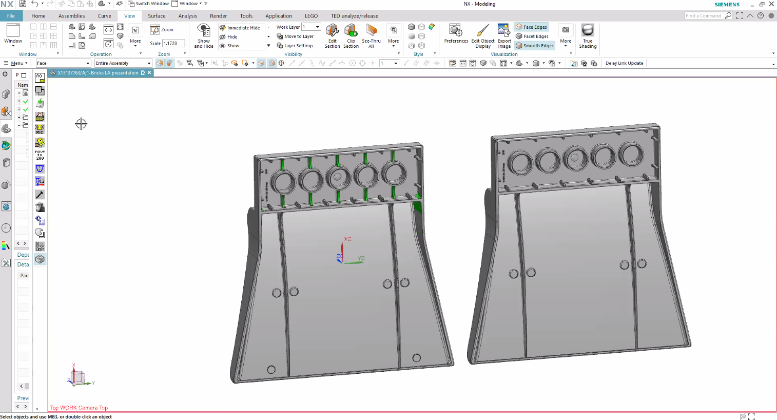
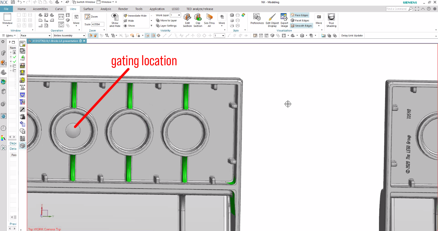
There are a couple of interesting things to point out here. In the third image, I have noted in red text where the gating location will be, indicated by the little convex disc shape you see in the center of the middle anti-stud tube. That means the injection point will be on the opposite side of this circle. Why the disc shape? Essentially, the shape will act as a backstop to the flow of molten plastic which is under extreme pressure. The disc shape also helps the flow of plastic to fan outward perpendicular to the injection point.
To demonstrate this idea, turn on your kitchen faucet to get a nice stream of water going. Hold a spoon under that stream so the water is hitting the concave side (how you normally hold a spoon) and watch the water splash outward. Apologies if you got wet!

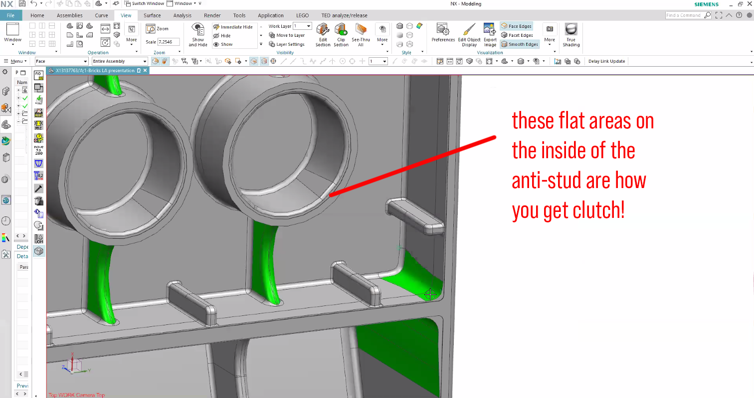
In the fourth image, I also pointed out the flat areas inside the anti-stud tubes. This is the secret to the magic of clutch power! These flat sidewalls are what engage the stud of another part and clamp onto it. What this really creates is called an interference fit, otherwise known in the fan community as clutch power!
Bridging the Gap

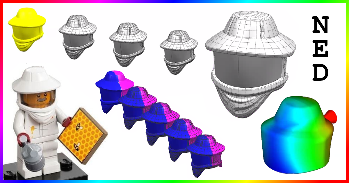
Next up, Andreas walked us through an example project using the Beekeeper hat from CMF Series 21 to demonstrate the work that NED must do to prepare the element for manufacturing. In this case, he received the part from the element design team already fully sculpted into the part the designers desire—but it isn’t ready to mold just yet.
The first step is to open the part in CAD and decide how it should be oriented in the mold. In other words, they have to decide where the parting line should be. (Parting lines are created where the two halves of the injection mold split to release the part.)
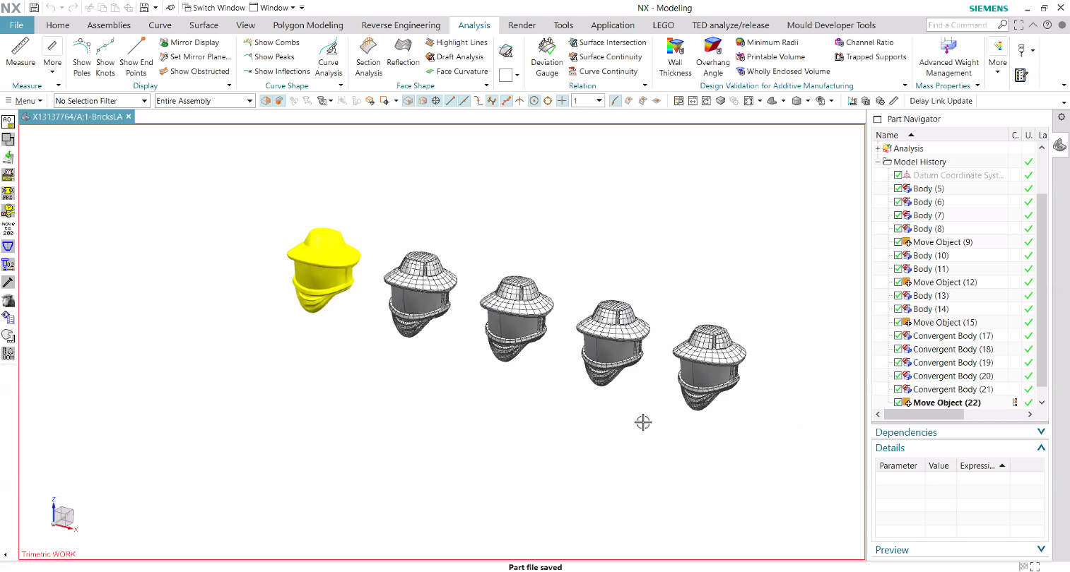
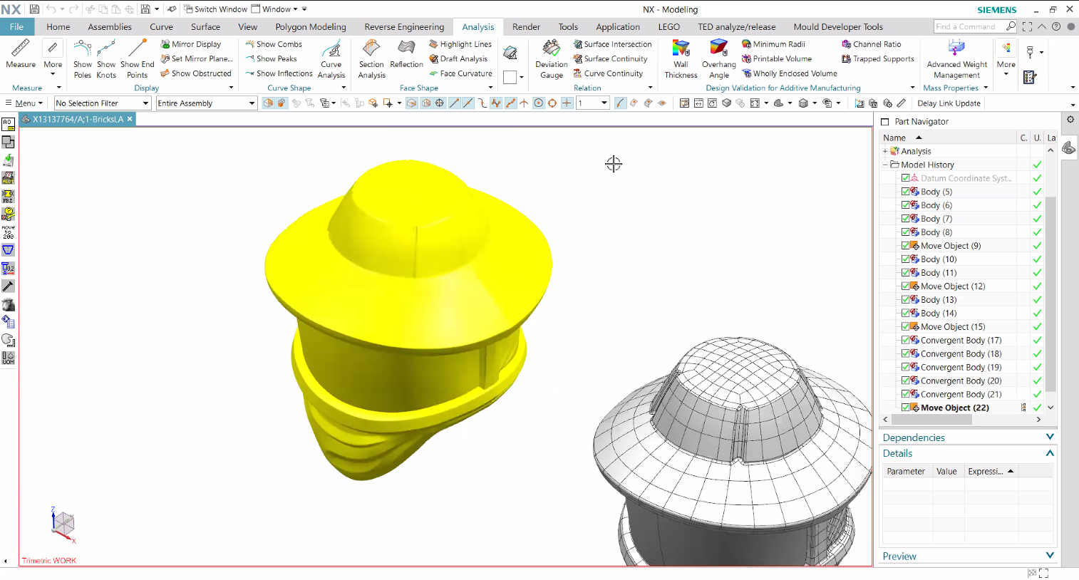
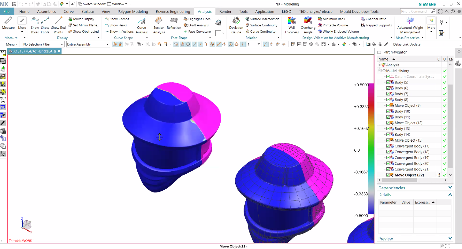
The first image above shows the “ideal” part they received, and the second image gives a closer look. The hat you see adjacent to the yellow highlighted model shows the contour of the part. It is how the CAD modeling software breaks up a complex sculpted surface into smaller surfaces. Image three shows the beginning of assessing where the parting line should be, in this case, splitting the part vertically from left to right. This is a 2K part, or 2-shot (dual-molded according to you AFOLs—more on that in a moment).
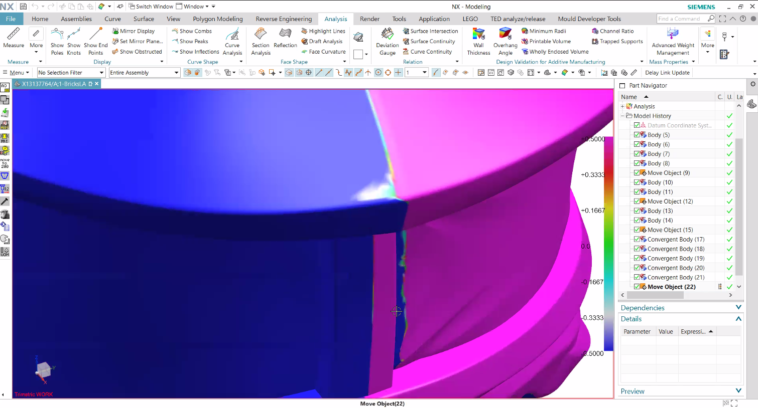
The first assessment of that parting line shows a very inconsistent line switching from pink to purple. The pink and purple indicate the two halves of the mold cavities. So in that current form, this part is not manufacturable. Image 4 even shows an undercut, which means we see a purple area inside the pink. If this part were molded as is, that undercut would drag against the mold during ejection and either get stuck in the mold or come out damaged.

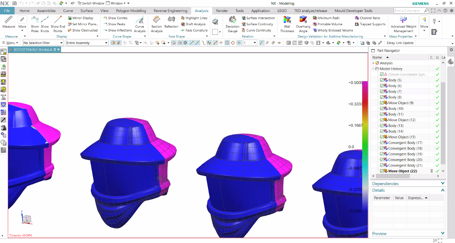
So the part had to be redesigned with a clean parting line and no undercuts, as shown in image 5. The below image also shows the two individual components that get molded together—the trans brown visor on the left and the white surrounding hat on the right.
Terminology
Let’s pause for a moment and come back to some terms used above to describe these two components being molded together. Most commonly in the plastics industry, this is called 2K or 2-shot. I’ve honestly never heard the term dual-molded until arriving into the LEGO community.
At this point, I think everyone knows what “dual-molded” refers to, and even Andreas references it since he is aware AFOLs use that term. But the LEGO engineers do call it 2K. Just a fun tidbit! (Here’s another BrickNerd article talking about “dual-molding.”)
Mold Filling Simulation
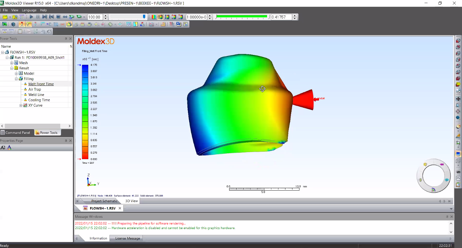
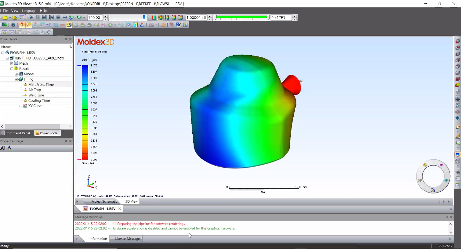
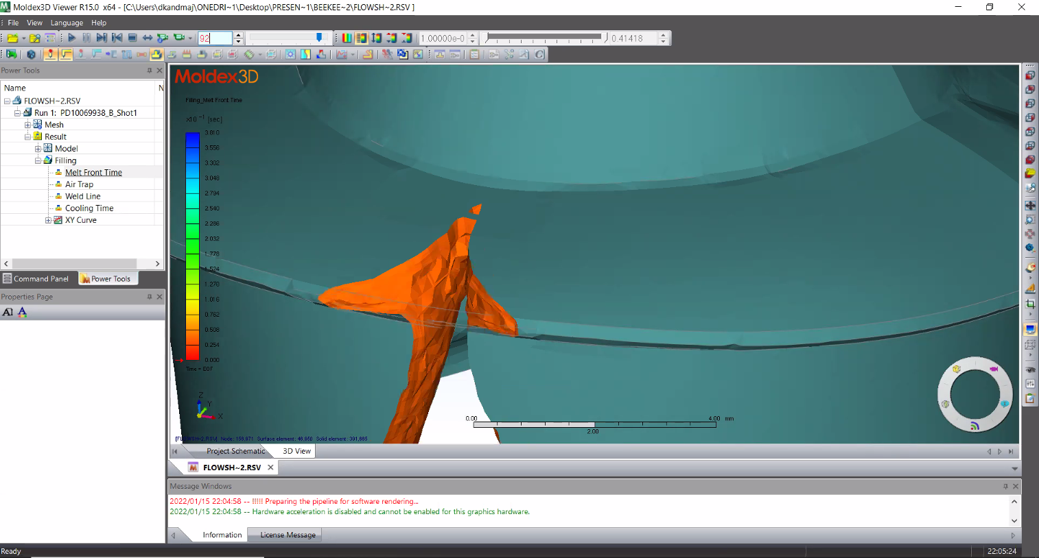
Moving on to the final steps, Andreas showed us a mold-filling simulation. In other words, the software takes the CAD model, applies the gate location, processes the parameters and much more data, and then simulates how the part would fill with molten plastic. This type of analysis has been around for a long while (and they are extremely accurate when done properly). Many different software brands do this, and in this case we get to see the LEGO team uses Moldex3D (my team uses Autodesk Moldflow).
The below images show the inner visor part after a simulation has already been done. The gating location is indicated by the red cone. The rainbow of colors helps to show accurate data, depending on what you want to display. In this case it is showing time for completing that first shot, the blue being the final area filled in since it is furthest from the gate.
Andreas even showed off a little live simulation of it filling!
Fun fact: where molten plastic meets other molten plastic within the mold furthest away from the gate (or injection point as AFOLs call it) are called knit lines. In some darker colors of plastic, these can appear as a kind of scratch even though the surface is completely smooth. You can tell they are knit lines if every piece has a similar marking (sometimes exactly flipped depending on the location of the part within the greater mold). Most commonly, the knit line is where a part could first fail or crack. You also might see what are called flow lines on parts molded in pearl gold and silver, as the fine glitter additives make these lines much more prominent on the final pieces—a challenge that they have had to work out with the newly released Orient Express since the set features quite a few new 1x6 plates and 3x3 window frames in pearl gold. Perhaps another article is required altogether, to talk about that!


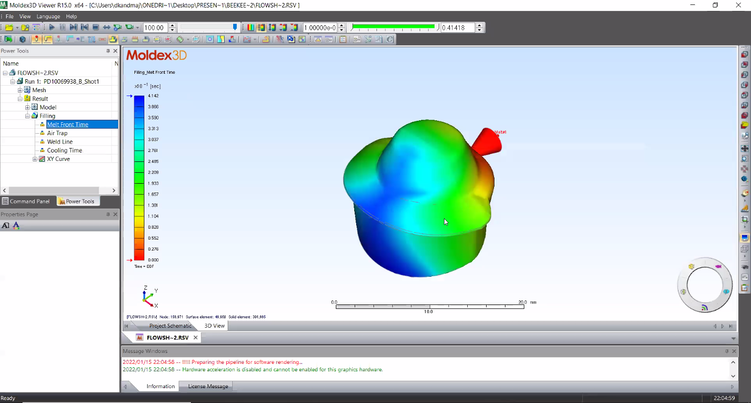
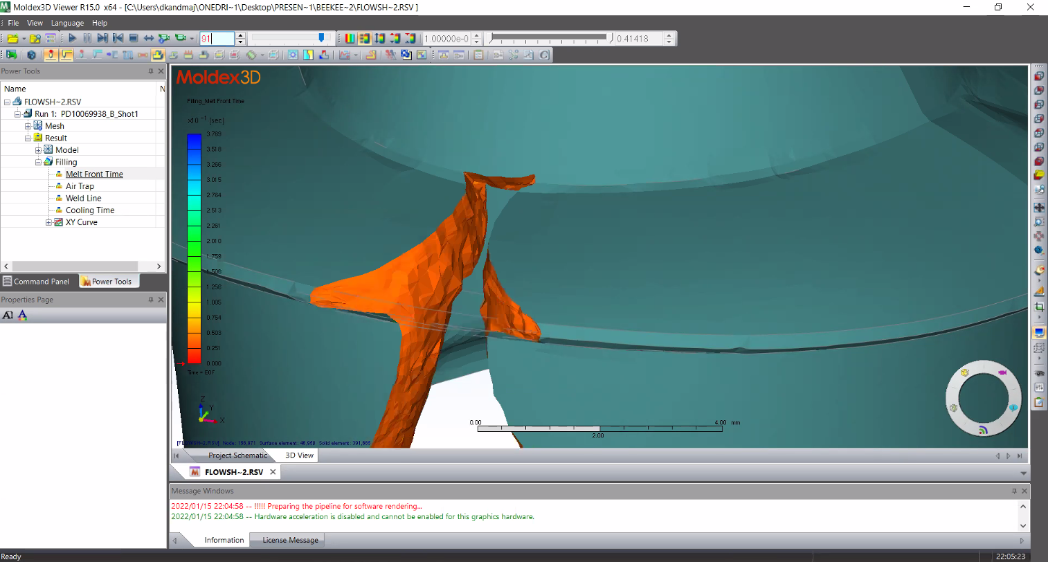
Lastly, Andreas showed us another simulation for the final iteration of the visor piece, describing an issue they had to overcome with an air trap (a tiny pocket visible in image three).

Here you can see the part design also changed a bit. You definitely don’t want air getting trapped during the injection molding process because it will be a defective part at the very least. At the worst, you can cause damage to the injection mold itself which is very expensive to repair.
Typically these traps are easy to overcome with a simple adjustment to the gating location. If that doesn’t do it, there are many other tricks like adjusting wall thickness, flow leaders, etc.
Go With the Flow
Sadly, the presentation by the NED team members ended there, even though I could watch plastic mold-filling simulations all day long! It is usually rare to get a behind-the-scenes view of internal processes like this from a company like LEGO, so I’m glad they were able to share what they did.
In reality, so much more goes on in the final stages of bringing LEGO part designs to manufacturing that wasn’t covered. Andreas briefly explained some of the next steps handled by the CAE department (Computer Aided Engineering). That team likely helps determine the exact molding procedures, cycle times, multi-cavity tool design, etc. (speaking from experience on my team). But those are topics for another day.
Personally, I have always loved manufacturing and its complexities. It is a real joy! This also shows that LEGO is more than just set and product designers. It takes an incredible amount of engineering prowess before a set designer can even hope to put two bricks together, and this presentation showed how they all work together and go with the flow. I hope my passion comes through in this article and that you were able to enjoy it and learn something new.
Best of BrickNerd - Article originally published on November 29, 2023.
Do you have a favorite LEGO element? Perhaps the reason you love it is because of the engineering that went into the development!
Do you want to help BrickNerd continue publishing articles like this one? Become a top patron like Marc & Liz Puleo, Paige Mueller, Rob Klingberg from Brickstuff, John & Joshua Hanlon from Beyond the Brick, Megan Lum, Andy Price, Lukas Kurth from StoneWars, Wayne Tyler, LeAnna Taylor, Monica Innis, Dan Church, Roxanne Baxter, and Steven Laughlin to show your support, get early access, exclusive swag and more.