Beam Me Up! Flexing With LEGO Beams
/Happy Engineers’ Week! To celebrate this year, we’re going to dive into beam theory!
Last summer, Oscar wrote an excellent article about building LEGO SHIPs where he dived into the strength of brick-built beams to support large space-faring MOCs. This has percolated in my brain for the last several months; and with some theory, experimentation, and math, we’ll learn what happens when you… abuse well-established engineering principles.
Beam Me Up!
Beams are long structural members that support loads perpendicular to their long axis. Think bridges, floor and ceiling joists, airplane wings, diving boards, and shelves to name a few common beams that may be in your everyday life. We are going to be exploring basic beam theory, which has some very specific assumptions and lots of math (that I will try to keep relatively simple and avoid the “Here be Calculus” parts of the map).

Beam Problem form Engineering Mechanics Statics 9th Ed by R C Hibbler One of my engineering text books
To begin, here is what you need to need to know about all the beams that will follow:
Material is homogonous – This is mostly true. I had to use different colors of bricks, which can have an effect on material properties, but it’s at least all ABS plastic.
Beams are straight – Easy enough to accomplish with LEGO.
Beams are long – The definition can vary, but length is at least 8 times width and height, so a 1x8 brick is a “beam,” but a 2x10 isn’t (for this definition, it can act as a beam, but the assumptions here and the math are not applicable).
Uniform cross section – This one we cheat on a bit. LEGO elements do not have a uniform cross-section. Since we will be building a beam longer than any one element, this introduces “degrees of freedom” points that are more susceptible to bending than a constant cross-section would; this is why our theoretical and experimental numbers do not line up.
Loads are perpendicular to the long axis and only in one plane.
Beams have at least one axis of symmetry along the long axis. Weird twisting effects occur otherwise, but this can happen with symmetric beams, too.

1×12 brick top, side, and bottom views
So, let’s simplify that. Think of a 1x12 brick, then we’ll go down the list. It’s made of one material; it’s straight; it’s long and skinny, it’s a mostly uniform cross-section; we’re going to load it from the studs down (perpendicular), and it is symmetrical about the long axis. It’s a beam!
We can mount our beam in two ways: simple supports or cantilevered. A simple support system is what Oscar did in his article with a LEGO beam suspended between tables on each side where the beam is free to slide as it deflects (the movement away from the starting shape) under load.

Oscar’s set-up.
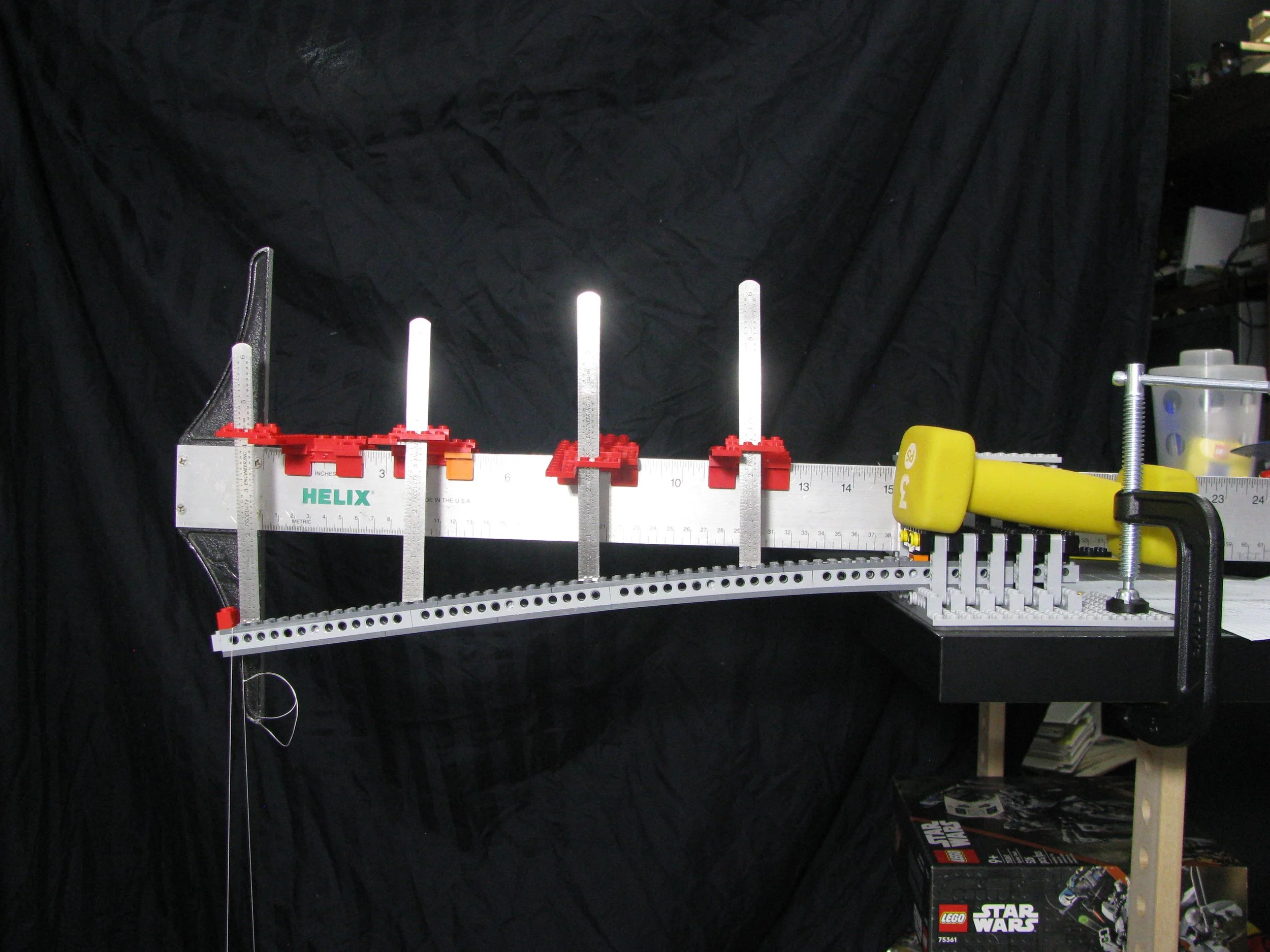
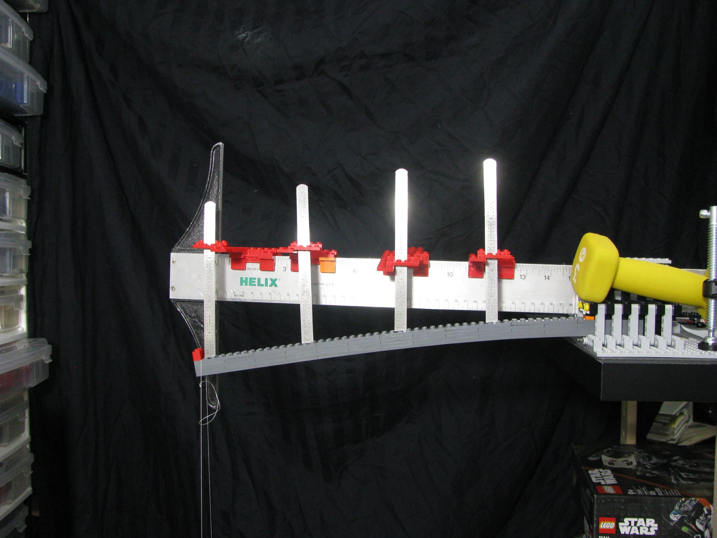
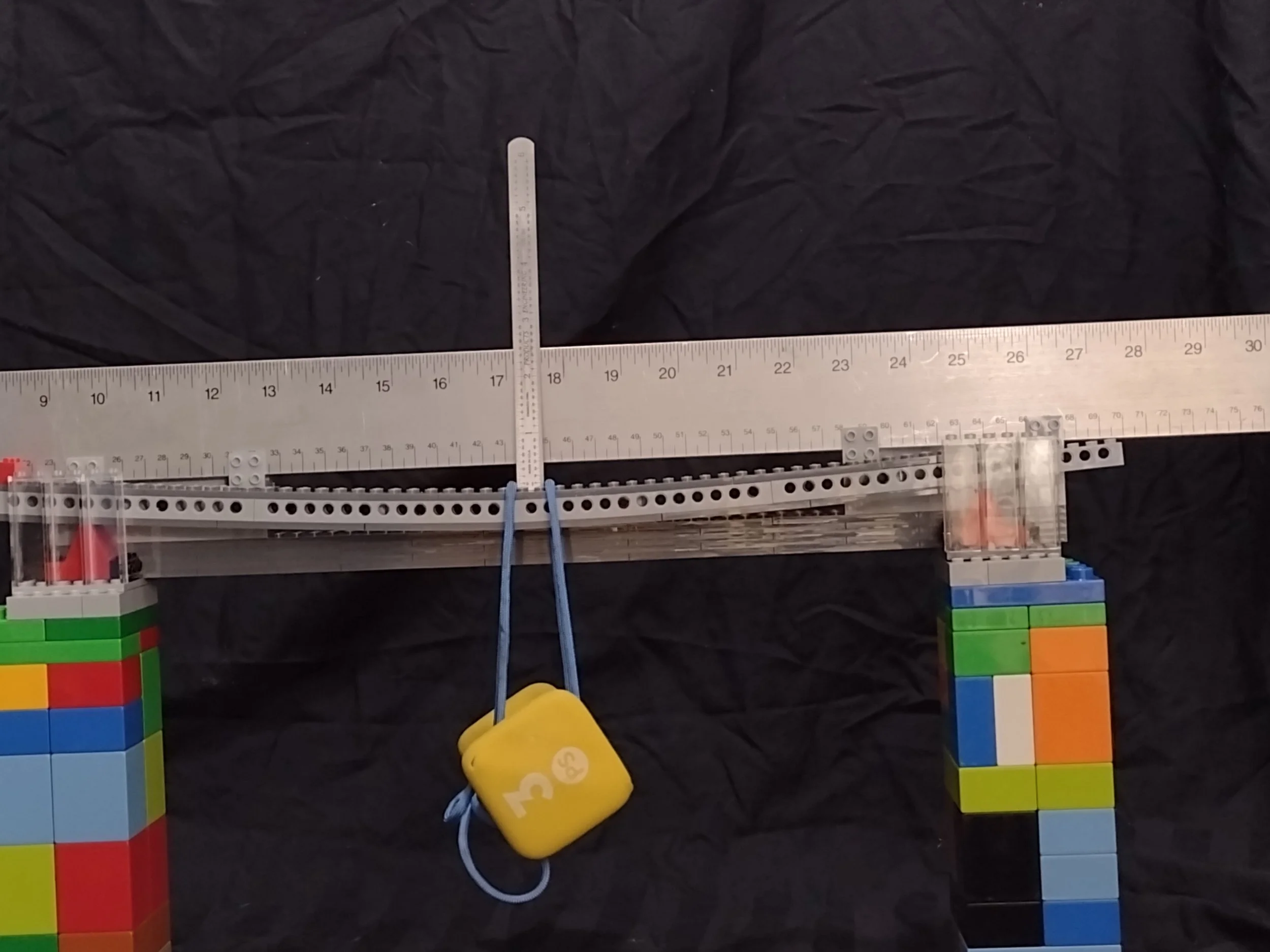
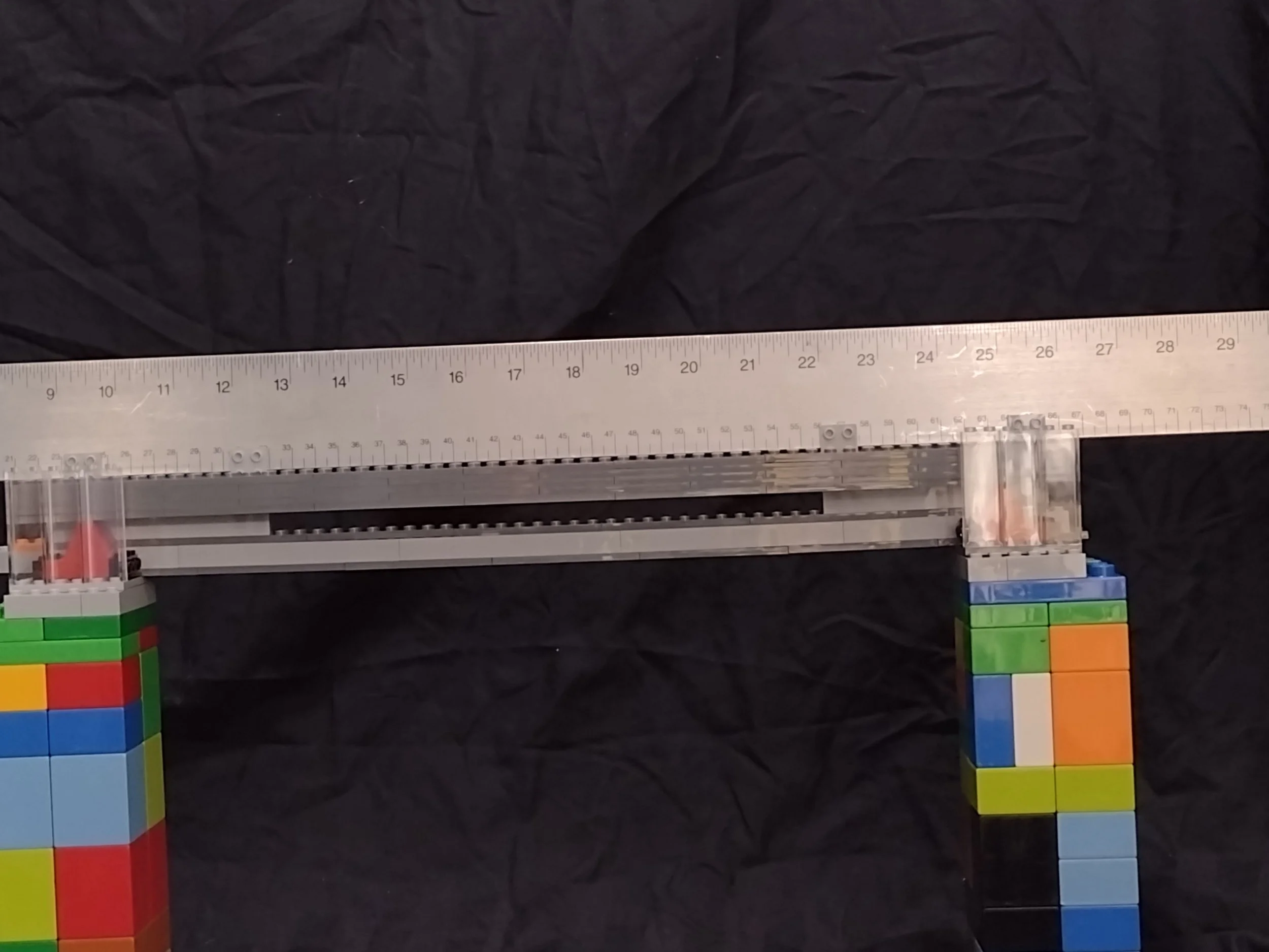
My experiments use cantilevered support, like a fence post, where one end is anchored so it can not move, and the other is free to deflect. This allowed me to work with shorter beams that fit my workspace.

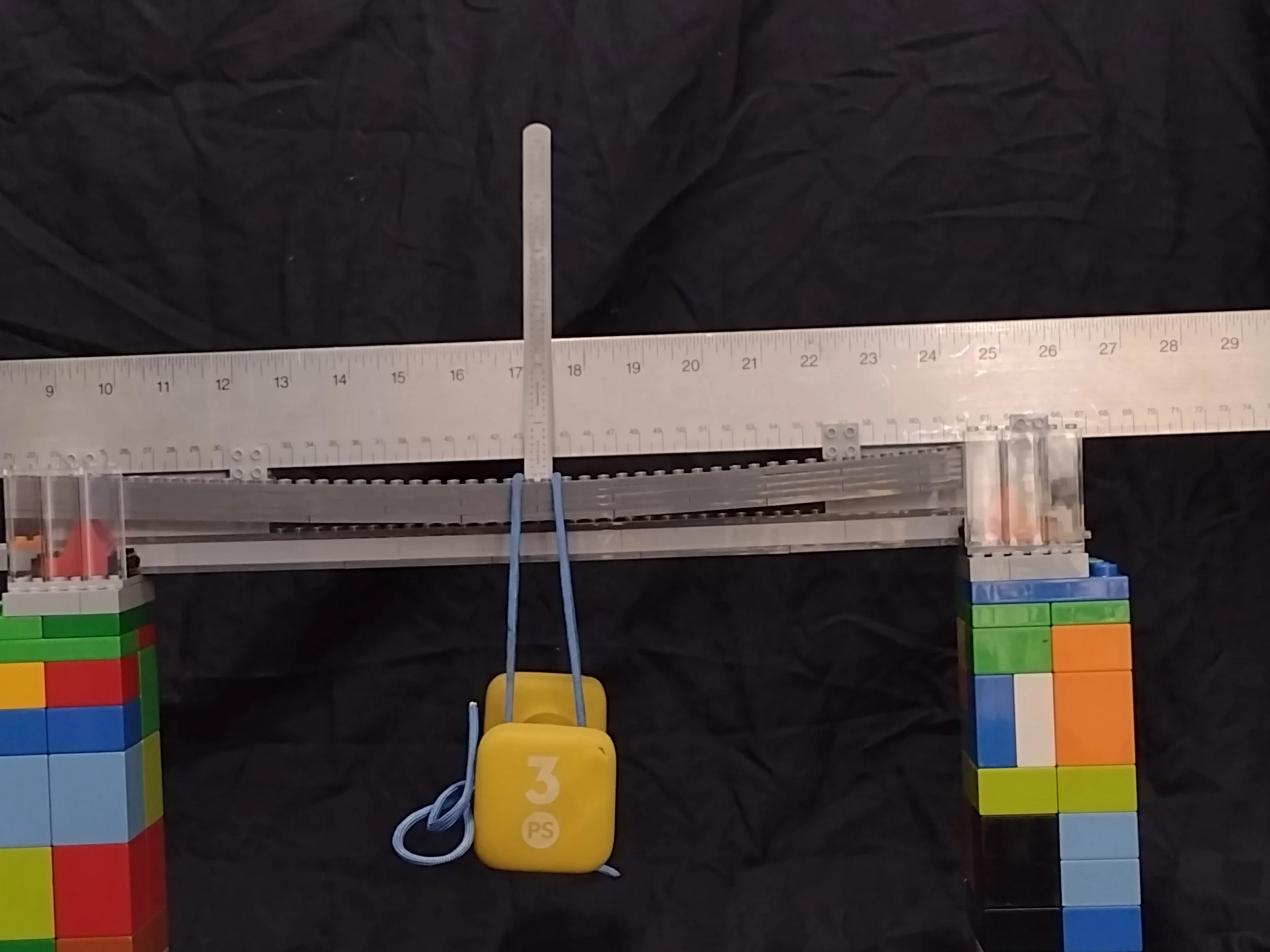
Oscar and I both used simple point loads to weigh down the beams. He had 4.4 lbs. (2kg) bucket of water, and I used a 17 oz (0.48 kg) can of tomato sauce. (My original plan was a 3 lb hand weight, but it broke the first beam, so changes were made—you use what you’ve got!).
Other options are a distributed load that would be the weight of the beam or, say, if you lay down on that diving board I mentioned earlier, or a moment, which is a torque or twisting action, but we won’t be exploring those today.
I Have A Theory!
As beams bend down, the top is put in tension (stretching) and the lower side is put in compression (squishing), so the top and bottom of the beam see the most stress.

This is why “I” shaped beams are common structural members. More material is in the caps of the I beam to transmit the stresses, and less in the web (the middle part). Now fair earning, if you are math-averse, you may want to skip to the “Testing” section of this article.
Bending stress which is what beams mostly handle is governed by the equation:

M is the bending moment (the load times a distance units of inch pounds or Newton meters. I don’t know why it is distance force in one system and force distance in the other).
C is the distance from the neutral axis (axis through the beam with zero stress).
I is the Moment of inertia (this has a couple of different names, but Moment of Inertia is the simplest and it is the integral of the area (Calculus fun!) It is in units of length to the 4th power inches^4 or meters^4) Simply put, it is a shapes resistance to bending. Fortunately for us for a rectangle the equation reduces to:

Moments of Inertia for complex shapes can be computed without too much headache, but the area of the shape and the distance from the centroid (think balance point or center of gravity) must also be taken into account. We’ll work through an example. (I apologize to our readers who live in the metric system—the math will all be presented in units of pounds, inches, and seconds.)


Which gets us to the final equation maximum deflection of a cantilevered beam with a load at the end is

P is the load; L is the length of the beam. (P∙L = Moment from above). The equation for getting the intermediate points used in the graph is a bit more complicated (and not shown for simplicity), but our goal is the total deflection, so we’ll move on.

Predicted Deflections
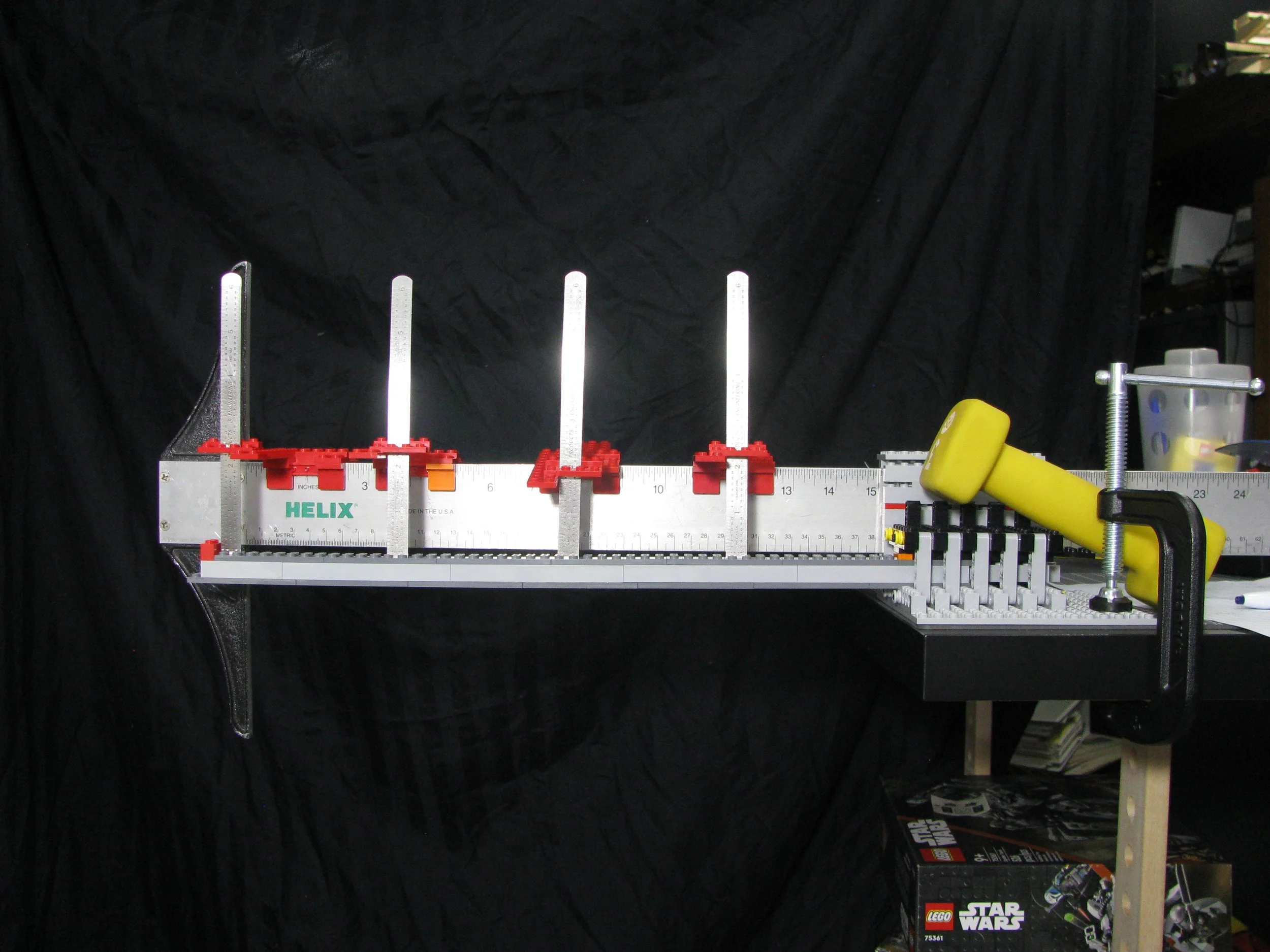
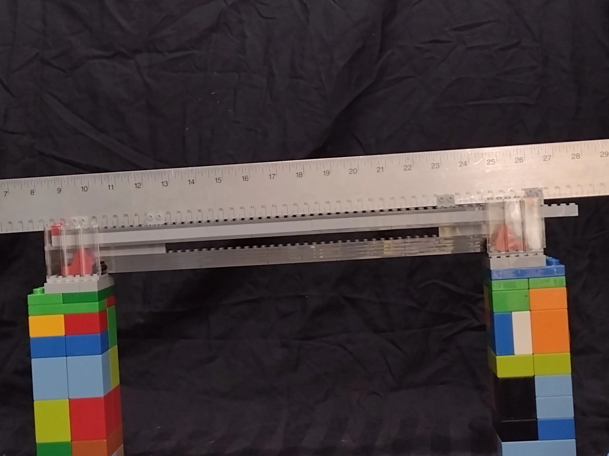
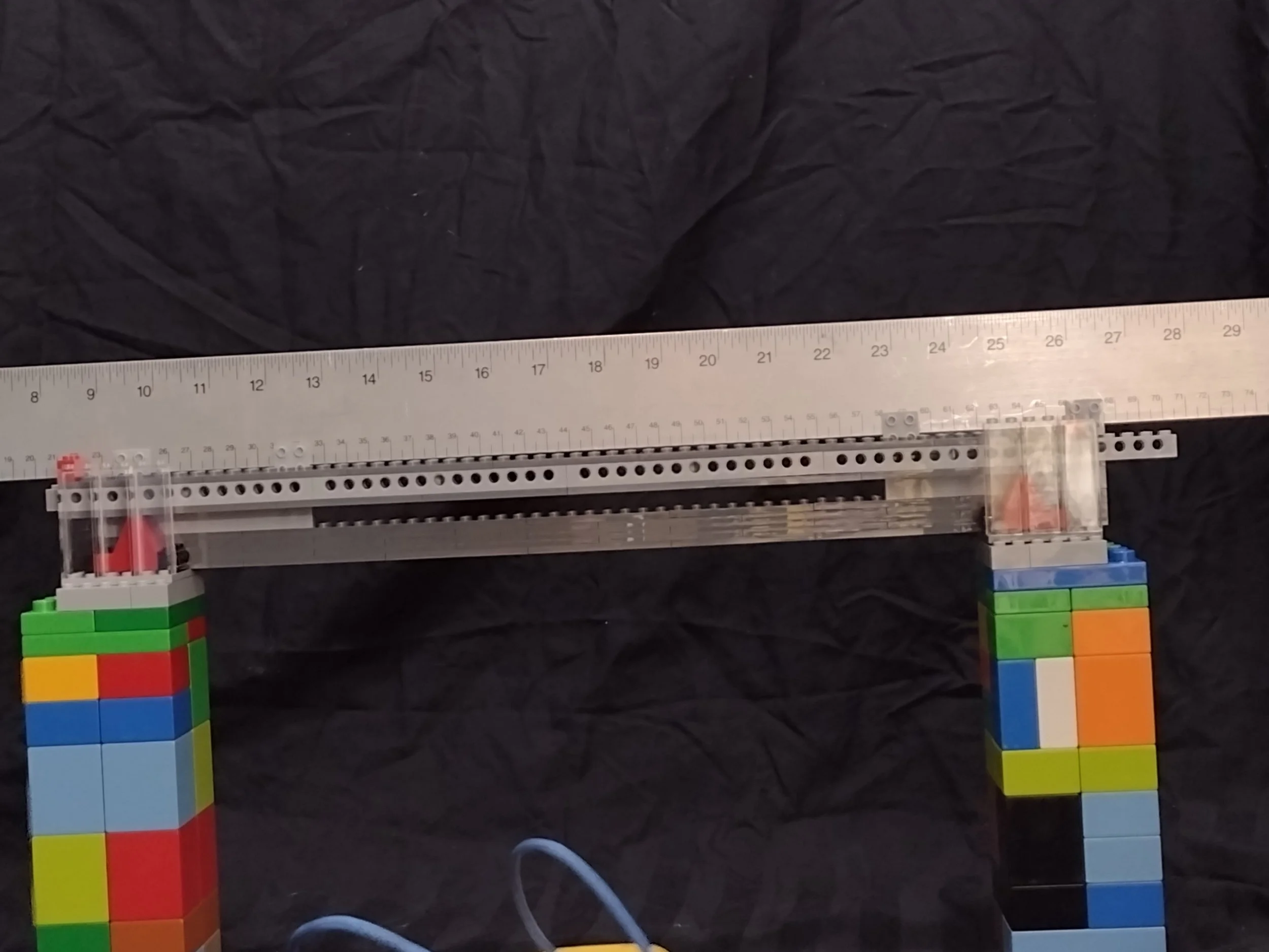
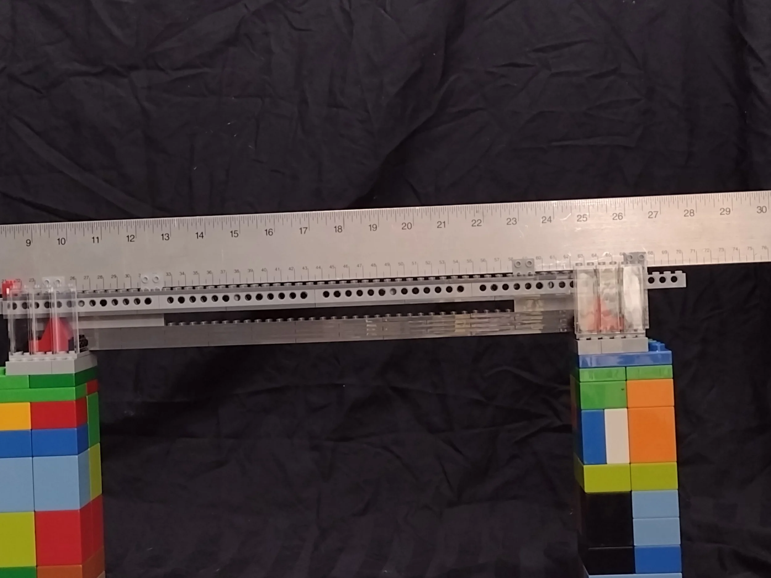
Testing Beams
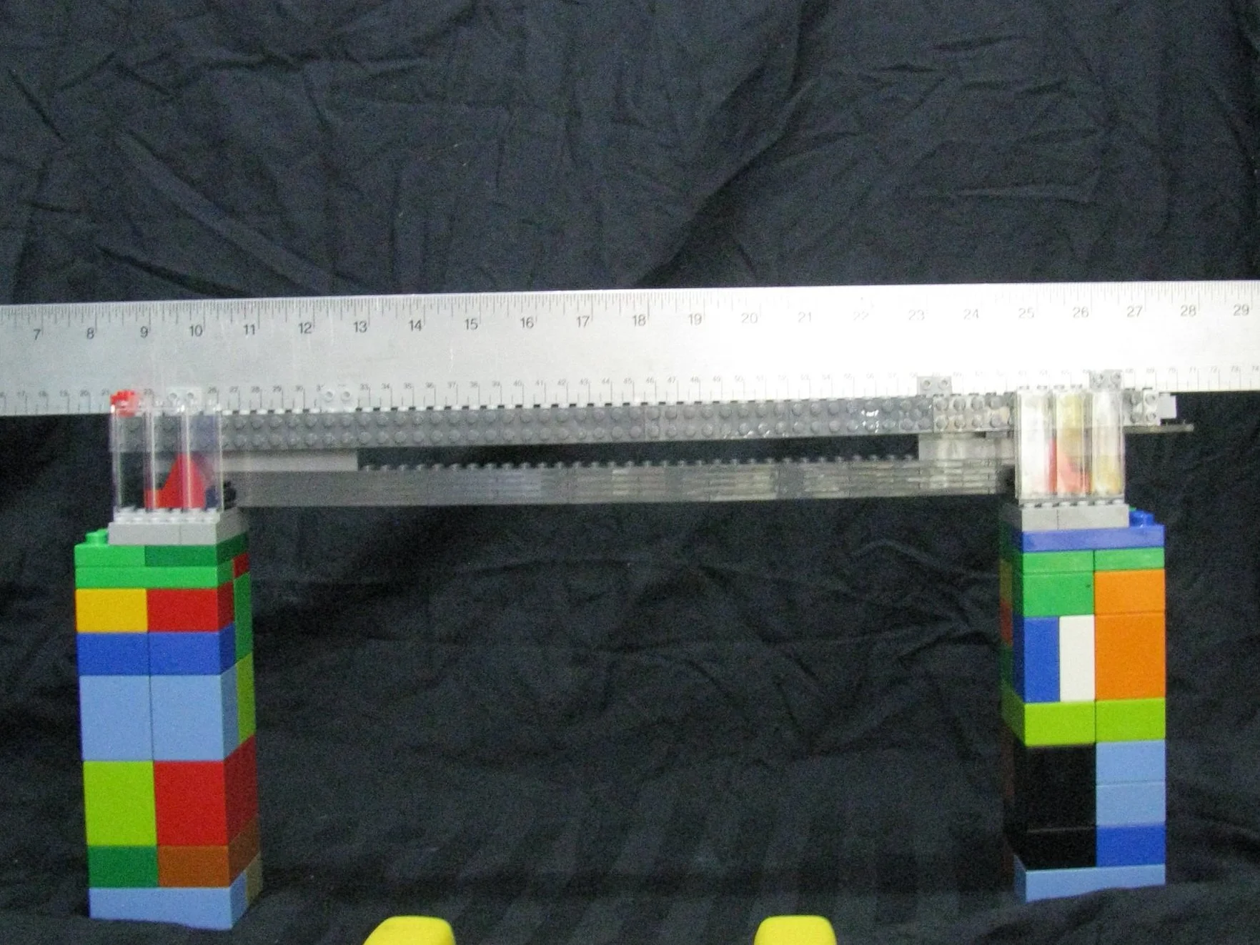
I tested five beams. For the sake of comparison, they are all approximately 2 studs wide and 5 plates tall, thus forming a square cross-section. I wanted to use all the same color bricks to minimize the changes in the Elastic Modulus (E) that the color additives may have caused, but I had to settle for light blush grey (LBG) bricks and dark bluish grey (DBG) plates. I did have to use a couple of GBG brackets because I ran out of LBG at the end. Beams A, B, and C are very similar as they are 1xX bricks with caps of 2x8 DBG plates.

Beam A uses standard 1x12 bricks, B uses 1x LBG Technic bricks without pins, and C uses 1x14 LBG technic bricks with pins. Beam D was a late add made mostly of 2x8 DBG plates (to be truer to the rest of the test, the middle 3 plates should have been LBG). Finally, Beam E is a core of 1x LBG bricks with 2x2x2 up and 2x2x2 down brackets (almost entirely LBG but there are a few DBG) alternating down the length, then the 2x8 DBG plates are applied to the brackets. This beam is slightly wider than the rest and is 5.5 plates wide versus the 2 studs/5 plates width of the other beams. A test length of 48 studs (15 inches / 381 mm) was used.
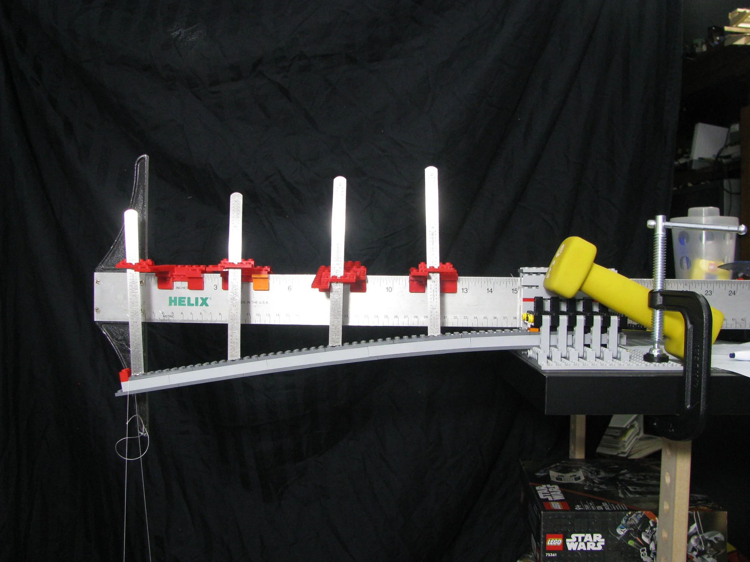
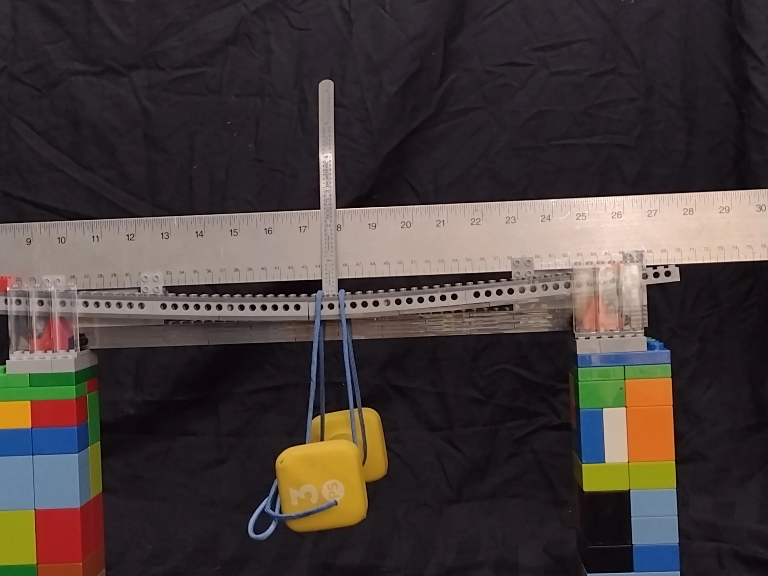
First up in testing was Beam A, and right away, I ran into trouble. The beam broke with the 3-pound (1.36 kg) hand weight I had initially chosen for a weight and several parts went flying off. I largely suspect this was because of the 2x8 plate having a joint at the fixture.
This is where Oscar’s simply supported beam test was a better choice, you don’t have to deal with the moment reaction. Anyway, I fixed the beam (I still haven’t found where that 2x8 plate flew off too), scrambled around the house for an alternate weight, and found a food can that came in at a nice even 17 oz (1.0625 lbs. / 482 g). My end deflection was 2” (50.8 mm). 2.98 times the prediction.

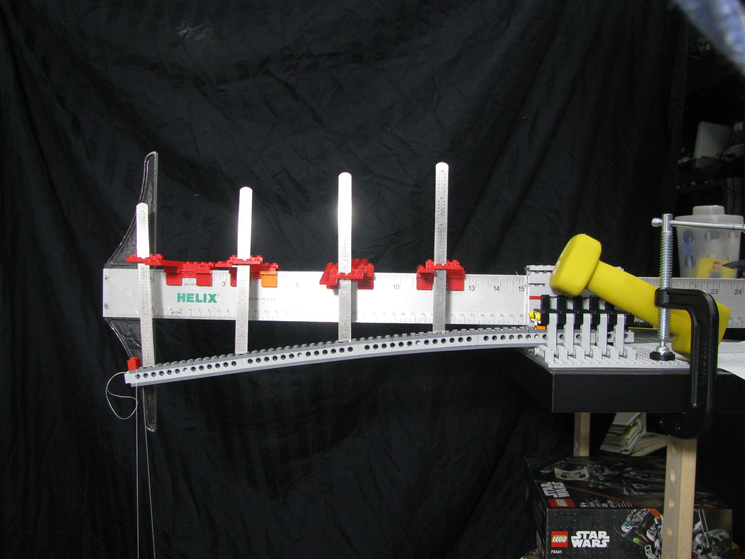
Beam B performed better—this was the Technic beam with no pins. The end deflection came out to be 1.5” (38.1 mm), with a difference of 2.23 times the calculated number. It wasn’t surprising since Technic beams are supposed to be stronger. I used the same moment of inertia for the Technic bricks and for regular bricks. The holes make things complicated (it is a more non-continuous cross section, but fortunately they are near the neutral axis where less stress is carried). There may be a more continuous section at the top of the brick that I could not accurately measure.
With Beam C, a surprise was had! It had more deflection than it’s no-pin counterpart. I was expecting the Technic pins to help the beam perform like a more continuous cross section and be stronger, but test deflection was 1.75” (44.5mm) or 2.61 times the prediction.
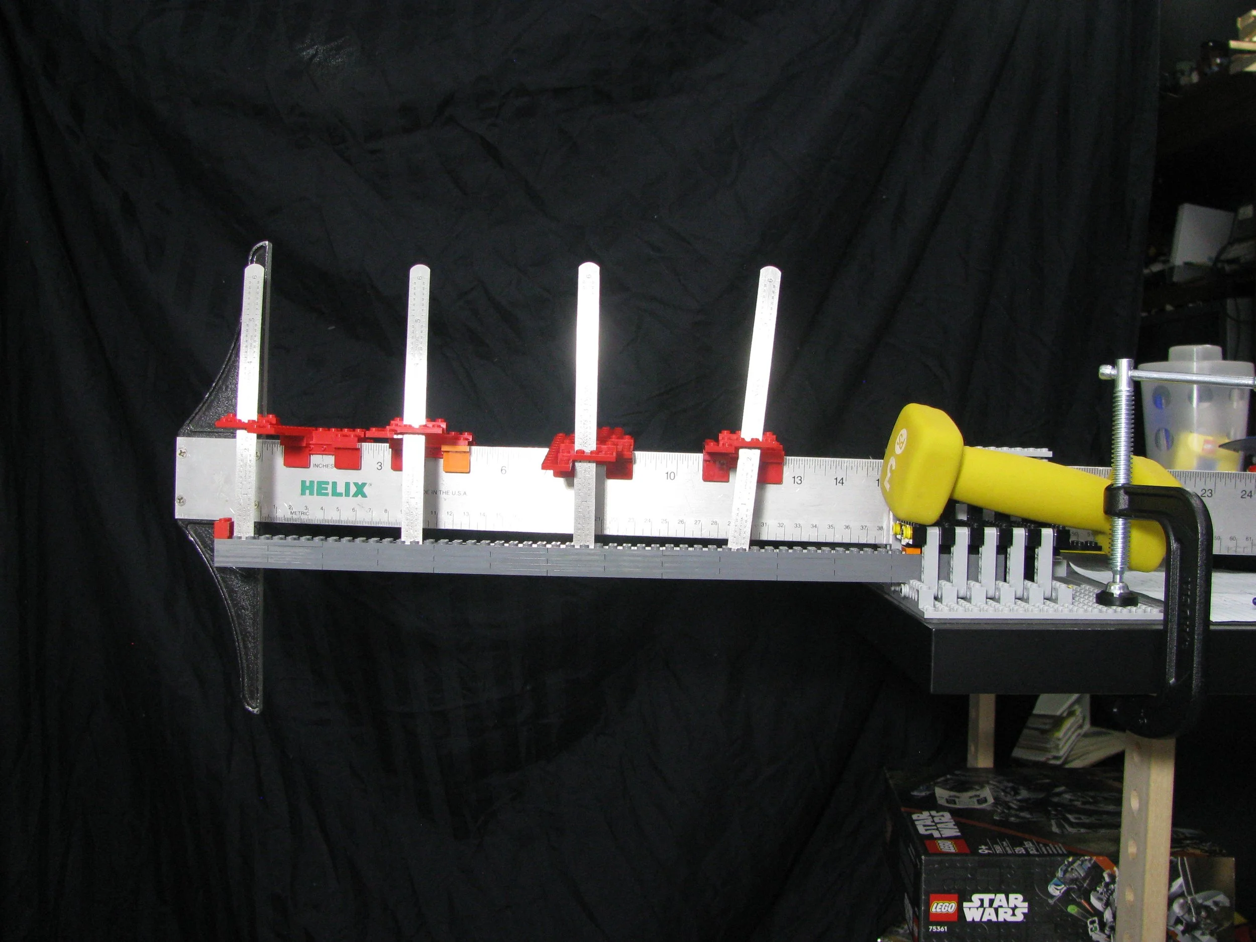
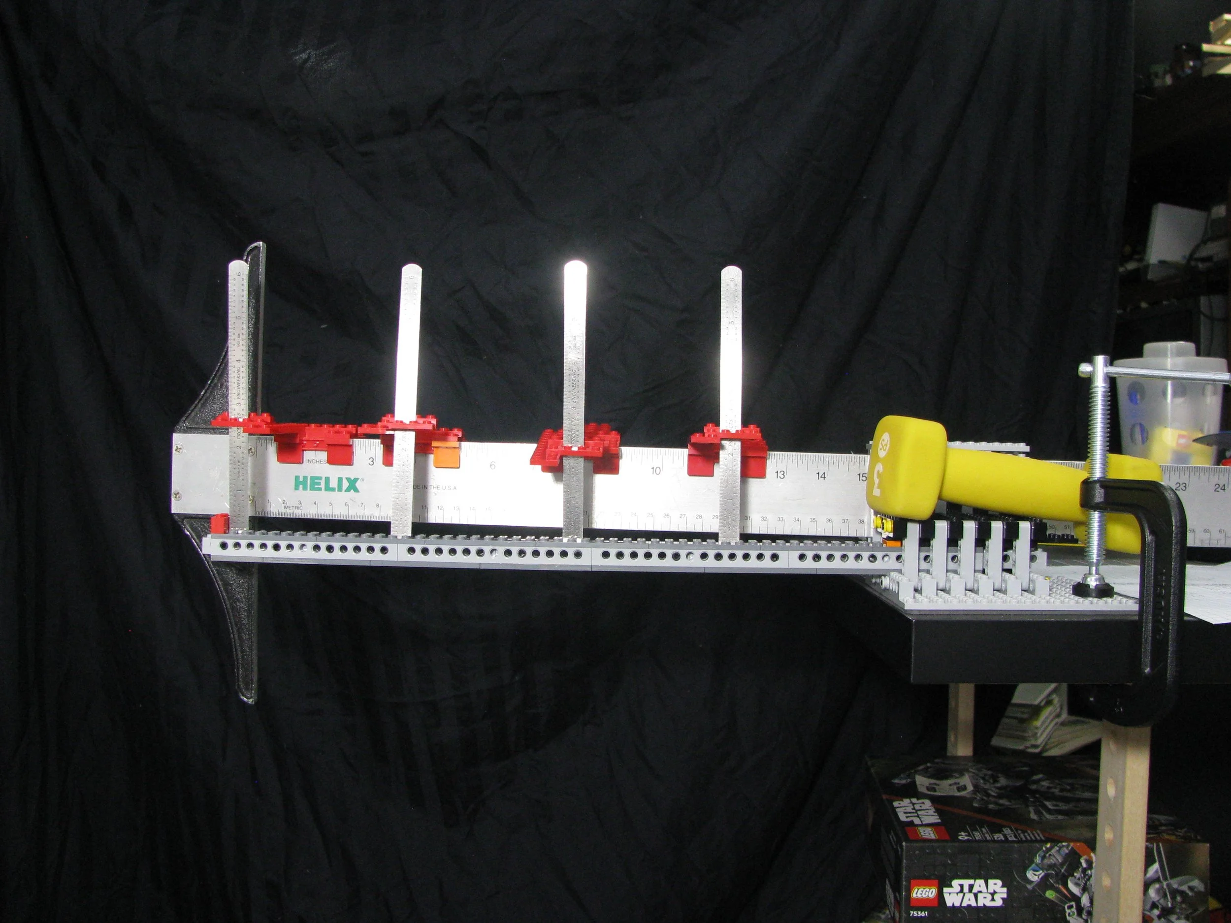
Beam D, the five-plate sandwich latecomer to the party, actually performed surprisingly well. I definitely expected it to fail with the 3-pound weight and wasn’t sure about the can weight. It had the highest predicted deflection but only bent 2” (50.8 mm) for a 2.78 ratio to the prediction.

Beam E had my highest hopes, built up in multiple directions with less than a half inch (13 mm) of predicted deflection. But what a heartbreaker—this beam had the largest deflection of all with 2.25” (57.2mm) an astonishing 4.75 factor to the prediction.

Predicted Vs Results

Oscar’s Beam C Technic and Plates
As a bonus, I calculated deflection for Oscar’s brick and plate beam as I had a moment of inertia handy. The equation is different for a simply supported beam with a center load. The predicted deflection is 1.39 inches (35.3 mm) He had a 46 mm deflection for only a 1.3 times factor. Hmm, something is going on here.

This got me curious, so I built a quick simply-supported test rig and retested all the beams, this time the 3lbs. (1.36 kg) weight worked, all deflections were around 0.5 in (13 mm), and the correlation to calculated was worse.


What Was That?
A couple of things are going on. First, there were likely errors on my part. As a rough guess, my deflection measurements are probably only good to +/- 1/16” (1.6 mm) at best for the cantilever beams. I was better at the simply supported but the smaller deflections make smaller errors have bigger impacts.
I’ve thought of several ways that I could have improved the accuracy of my readings. While I thought my T-square was level, I did not check it with a level in between tests. Despite having a 3-pound counterweight, a C-clamp holding the fixture to my table, and the beams being locked in over a 12-stud length, my support was likely not perfectly rigid.

Next are the stresses that develop in the beams themselves. You may have noticed that the coefficient in the deflection equation is very different—the cantilevered equation has a 3 in the denominator versus the 48 in the simply supported equation. A simply supported beam has 16 times less deflection for the beam if everything else is kept the same!
A common visualization tool engineers use is a shear and bending moment diagram. Shear is the internal load transmission of the load(s) P to the reaction points or supports (R). Moment is the bending force created. Below are the shear and bending moment diagrams for a cantilever beam (right) and a simply supported beam (left). The cantilever beam must transmit all the load as shear to the single support, and the longer the beam, the more moment is built up.
The simply supported beam has two supports to share the load, which if it is centered, is split equally. The supports of a simply supported beam do not react moments. (If you make a beam that is fixed at both ends the math gets really ugly. This is called a statically indeterminate beam) The centered load split between the two supports builds up only a quarter of the maximum moment.

The difference in the shear and bending moments explains why Oscar and I got such differing results, but why do both of us see more deflection than predicted? This goes all the way back to the beginning of points 1 and 4 in the definitions / assumptions of what is a beam! The LEGO beams aren’t entirely homogeneous as discussed; the additives for different colors can affect the material properties; and the cross-section isn’t continuous.
The bricks and plates have varying cross sections which creates stiffer and less stiff sections. This means our moment of inertia varies the length of each LEGO element. Furthermore, the ends of each part are much stiffer as they are a rectangle. Followed by the gap between bricks which is “soft”. All these little changes in stiffness have an impact on the total stiffness of the beam. These changes introduce “degrees of freedom” into the structure, so instead of one solid beam, it is more like a bunch of small beams with little hinges throughout. Each hinge has the ability to move a little but ultimately weakens the structure allowing for more bending.
Really these point load tests only give an idea of the general strength of a given beam, with each brick being its own single point load connected to the beam structure. The real loading of a LEGO MoC is going to be a distributed load spread across the length of the beam. Maybe a bit more like this:

So Class, What Did We Learn?
I learned that if I’m going to do an experiment write-up, I need to test my experiment out a little better! I hope you learned a little about what literally supports the world around you. And the next time you pass over a bridge, wonder at a building, or need to build a stronger MoC, knowing a little of the math behind it all makes you appreciate it just so much more.
Do you have any engineering questions Michael can try to answer? Let us know in the comments below.
Do you want to help BrickNerd continue publishing articles like this one? Become a top patron like Marc & Liz Puleo, Paige Mueller, Rob Klingberg from Brickstuff, John & Joshua Hanlon from Beyond the Brick, Megan Lum, Andy Price, Lukas Kurth from StoneWars, Wayne Tyler, LeAnna Taylor, Monica Innis, Dan Church, Roxanne Baxter, and Steven Laughlin to show your support, get early access, exclusive swag and more.